article
Wire ropes: how elevators hang safely from twisted steel
See how elevator wire ropes share load, grip traction sheaves, survive repeated bending, and provide inspectable, redundant suspension.
Published Jul 14, 2026
Stand beneath a stopped elevator and the car feels like a rigid room. Above it, however, the load may be hanging from several flexible steel ropes, each made from hundreds of much smaller wires. That sounds fragile until you see the engineering idea: many small elements share the work, bend around a sheave, reveal damage gradually, and provide redundancy that one solid bar cannot.
An elevator wire rope is not merely steel cable chosen by diameter. Its wire grade, strand pattern, core, lay, lubrication, terminations, sheave grooves, tension balance, and inspection rules form one system. The rope carries the car, but safe elevator motion also depends on the traction machine, brake, overspeed governor, car safeties, controls, guides, and buffers. No responsible design treats the suspension ropes as the only safety layer.
From tiny wires to a load-carrying rope
A wire rope is assembled in levels. Individual high-strength steel wires are helically laid into strands. Several strands are then laid around a core. The core may support the strands, help retain lubricant, and keep the rope's cross-section stable. Elevator ropes use constructions selected for traction, flexibility, fatigue resistance, dimensional stability, and compatibility with the sheave and service environment.
The helical geometry is important. A solid 10 mm steel rod could carry tension, but repeatedly forcing it around a sheave would create severe bending stress. A rope divides that cross-section into many small wires that can shift slightly relative to one another as the rope bends. Smaller wire diameter improves flexibility, while the complete rope still provides a large metallic area for axial load. That benefit brings a tradeoff: more wire contacts mean more internal rubbing, so lubrication and correct groove support matter.
The direction and length of the helices are called the lay. A regular-lay rope arranges wire direction within each strand opposite to the strand direction around the core. This tends to give stable handling and is common where rotation resistance and predictable behavior matter. The exact construction must match the elevator designer's and rope manufacturer's requirements; two ropes with the same outside diameter are not automatically interchangeable.
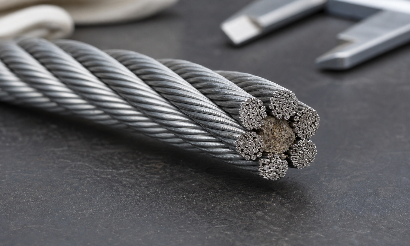
Figure 1. A representative rope construction separates the load into many small wires. The core supports the surrounding strands, while the helical arrangement lets the rope bend more readily than a solid bar of similar diameter.
How the car is suspended
In a common traction elevator, several ropes connect the car and counterweight and pass over a driven traction sheave. The machine turns the sheave; friction and groove pressure transfer force to the ropes. The counterweight offsets the empty car plus a chosen portion of rated load, reducing the motor torque and energy needed in normal service.
Multiple ropes are used for load capacity and redundancy, but their presence does not guarantee equal sharing. If one rope is shorter or its termination is adjusted differently, it can carry more tension than its neighbors. That rope then presses harder into its groove, stretches differently, and may fatigue faster. Installers therefore set and periodically compare rope tensions rather than dividing the total load by rope count and assuming reality will follow the arithmetic.
Roping arrangement also changes the mechanics. In 1:1 roping, car travel and rope travel are equal. In 2:1 roping, moving sheaves create two supporting rope parts for the car, so the car moves about half the rope speed while the load paths and bearing reactions change. The following example deliberately uses a simple 1:1 arrangement.
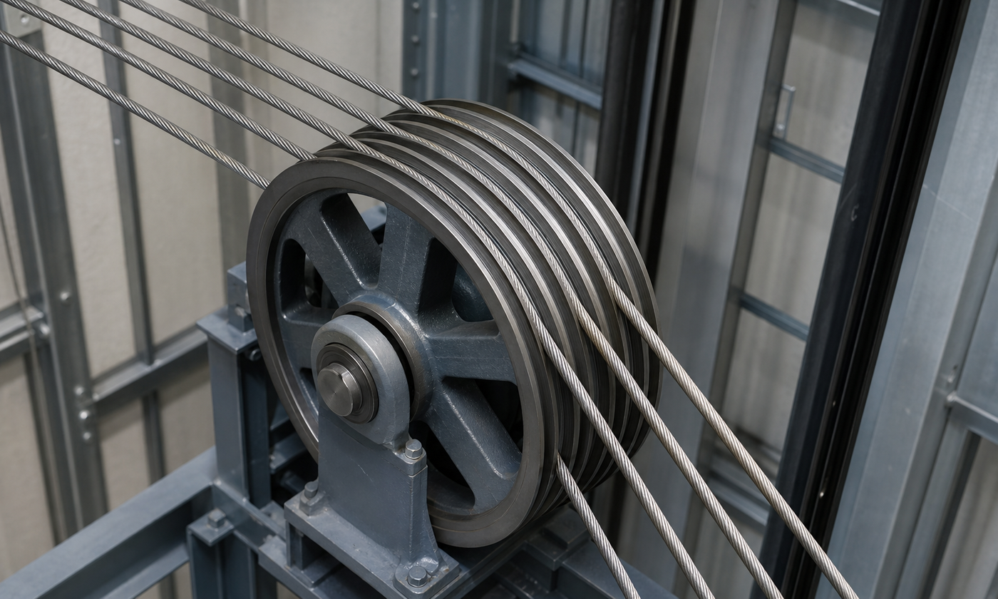
Figure 2. Each suspension rope follows its own sheave groove. Safe operation depends on continuous rope paths, compatible groove geometry, and reasonably equal tension across the rope set.
Worked example 1: load carried by each rope
Consider an invented 1:1 traction elevator with a 1,400 kg car, a 1,000 kg rated passenger load, and six suspension ropes. At rated load, the car-side suspended mass is:
car-side mass = 1,400 + 1,000 = 2,400 kg
The static car-side weight is:
W = m g = 2,400 × 9.81 = 23,544 N
If all six ropes share perfectly, the static tension per rope is:
T = 23,544 / 6 = 3,924 N = 3.92 kN
For a preliminary running-load screen, assume a 1.15 multiplier for acceleration and other modest dynamic effects:
screening tension = 1.15 × 3.924 = 4.51 kN per rope
Now suppose the chosen 10 mm rope has an assumed metallic area of 40 mm². The average axial stress over that metallic area would be:
average wire stress = 4,510 / 40 = 113 N/mm² = 113 MPa
This is not a rope selection calculation. Local wire contact, bending, residual manufacturing stress, unequal sharing, terminations, fatigue, wear, and code safety factors are not captured by average stress. If one rope carries 15% more than the ideal share, its screening tension becomes 1.15 × 4.51 = 5.19 kN. The example shows why tension equalization is an engineering requirement, not a cosmetic adjustment.
Traction: grip without fastening the rope to the sheave
The ropes are not normally bolted to the traction sheave. The sheave transfers force through rope-to-groove contact. A useful first intuition comes from the capstan relation:
T(high) / T(low) ≤ e^(μθ)
Here μ is an effective friction value and θ is wrap angle in radians. The relation says that more wrap and more friction allow a larger tension ratio before slip. Real elevator design is more involved because groove shape changes normal pressure and traction, rope stiffness is finite, conditions vary with wear and contamination, and the system must also avoid excessive rope and sheave damage.
Worked example 2: a simplified traction check
Use the same 1,400 kg car and 1,000 kg rated load. Assume the counterweight equals the empty car plus 45% of rated load:
counterweight mass = 1,400 + 0.45 × 1,000 = 1,850 kg
At full load, the heavier car side is 2,400 kg, so the static tension ratio is approximately:
full-load ratio = 2,400 / 1,850 = 1.297
At empty car, the counterweight is heavier and the reversed ratio is:
empty-car ratio = 1,850 / 1,400 = 1.321
For illustration only, take an effective friction value of 0.10 and 180 degrees of wrap, so θ = π rad. The simplified traction capacity is:
e^(0.10π) = 1.369
Both static ratios are below 1.369, but the empty-car case has the smaller apparent margin: 1.369 / 1.321 = 1.036, only about 3.6% on this oversimplified basis. Acceleration, braking, groove geometry, rope condition, lubrication, and code-prescribed cases could consume that margin. An engineer would therefore use the specified elevator traction method and verified component data, not approve the system from this one equation.
Bending fatigue sets the quiet limit
Every trip bends each rope as it enters a sheave and straightens it as it leaves. Wires on the outside of the bend extend; wires toward the inside shorten. Repeating that strain creates bending fatigue. The ratio of sheave pitch diameter D to rope diameter d, written D/d, is a useful flexibility indicator. A 500 mm sheave with a 10 mm rope has D/d = 500/10 = 50. A larger ratio generally reduces bending severity, but it increases machine size and does not replace construction-specific guidance.
Reverse bends, small deflector sheaves, poor alignment, worn grooves, and high tension accelerate fatigue. Groove fit is especially delicate. A groove that is too tight pinches the rope and raises contact stress; one that is too wide may provide poor support or alter traction. Unequal groove wear can also create different effective sheave diameters, forcing nominally parallel ropes to travel slightly different distances.
What inspectors look for
Wire ropes usually give observable warnings, but those warnings must be sought systematically. Common concerns include:
- Broken outer wires: fatigue breaks often cluster near sheaves or other high-bending locations.
- Diameter reduction: wear, core change, or internal deterioration can reduce measured rope diameter.
- Rouging and corrosion: reddish debris can indicate internal fretting or oxidation even when the outside still looks orderly.
- Unequal tension: one rope may sit deeper, vibrate differently, or show faster wear than the rest of the set.
- Distortion: kinks, birdcaging, flattened areas, protruding core, or damaged terminations change the intended load path.
- Sheave-groove wear: a new rope on a badly worn groove can inherit poor contact and shortened life.
Lubrication is controlled rather than generous. Too little can increase internal fretting; unsuitable or excessive lubricant can change traction and attract contamination. Maintenance teams use products and quantities approved for the rope and elevator system. They also inspect end connections because a strong rope is only as useful as the termination that transfers its load.
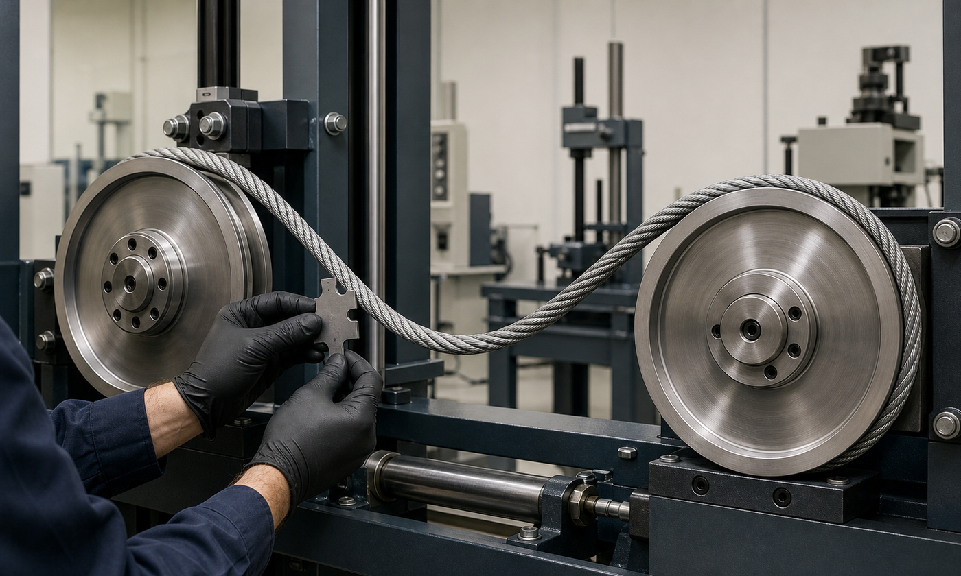
Figure 3. Rope condition, sheave geometry, and bend history are linked. Inspection combines visual evidence with diameter, groove, tension, and termination checks rather than relying on appearance alone.
How standards treat elevator ropes
Elevator safety codes such as ASME A17.1/CSA B44 in North America and the EN 81 family in Europe treat suspension members as part of a complete safety system. Product standards such as ISO 4344 address steel wire ropes for lifts. The applicable edition and local adoption matter, so a project must follow the authority having jurisdiction rather than a remembered rule from another installation.
In practical terms, the standards and manufacturer instructions control topics such as rope suitability, number and arrangement of suspension members, traction, sheave compatibility, terminations, safety factors, inspection intervals, and retirement criteria. Retirement is not based only on the first visible broken wire or on calendar age. It considers the location and concentration of breaks, diameter loss, corrosion, distortion, traction condition, and other evidence defined for the installation. Replacement can involve the complete rope set because mixing new and worn ropes may create different stretch, diameter, and load sharing.
Engineering judgment: think in systems, not rope strength
A beginner may ask, “Is this rope strong enough?” A practicing engineer asks a longer chain of questions. Does the rope construction match the sheave and duty? Are all ropes sharing load? Is traction adequate in the most unfavorable car and counterweight condition? Are bending cycles and D/d reasonable? Can maintainers inspect the critical zones? Are the grooves and terminations healthy? Do the brake, governor, safeties, and controls provide independent protection?
The most useful lesson is that elevator safety comes from controlled degradation and layered defenses. Hundreds of wires make the rope flexible; multiple ropes share the suspension duty; inspection finds wear before it becomes loss of function; and independent safety devices address hazards beyond normal suspension. For more original explanations of machine elements and engineering decisions, continue through the EnggTools engineering articles.