article
V-belts vs flat belts vs timing belts: choosing the right drive
A practical beginner-friendly comparison of V-belts, flat belts, and timing belts, including speed, tension, selection, installation, and failure clues.
Published Jul 12, 2026
A workshop fan, a textile spindle, and a small indexing table can all use two pulleys joined by a flexible loop, yet the correct loop may be completely different in each machine. Choosing between a V-belt, a flat belt, and a timing belt is really a choice about how the drive should create traction, whether slip is acceptable, and what kind of failure the machine can tolerate.
The three types are not simply old, ordinary, and premium versions of the same product. A V-belt wedges into a groove, a flat belt relies on surface friction over a broad face, and a timing belt engages teeth. Those different contact mechanisms control their speed accuracy, noise, bearing load, installation sensitivity, and useful operating range.
Three belts, three ways to transmit force
A belt carries power because the tight side pulls harder than the slack side. For a friction drive, the pulley surface transfers that difference in tension through friction. A V-belt increases the available friction by pressing its sloping sidewalls into a matching groove. This wedge action gives substantial grip in a compact pulley, which is why V-belts are common on pumps, fans, compressors, and general industrial equipment.
A flat belt contacts a smooth pulley across its width. It has no wedge multiplication, so it normally needs more wrap, width, or tension for the same duty. In return it bends easily, runs smoothly at high belt speed, and wastes little energy in repeated compression. Long-center drives, high-speed machinery, and conveyors can benefit from those qualities.
A timing belt, also called a synchronous belt, uses molded teeth that mesh with pulley grooves. Under normal design conditions it does not depend on slip to transmit motion. It can therefore preserve an exact angular relationship between shafts, making it useful for indexing, coordinated axes, packaging machinery, and engine cam drives. Its price for accuracy is greater sensitivity to tooth profile, alignment, debris, and shock loading.
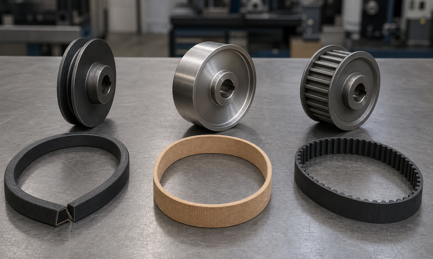
Figure 1. The pulley reveals the contact mechanism: a groove for the V-belt, a broad smooth face for the flat belt, and accurately spaced teeth for the timing belt.
The equations they share—and the one they do not
Ignoring slip and using pitch diameters, any two-pulley belt drive follows the same geometric speed relationship:
n2 = n1(D1/D2)
Here n is rotational speed and D is pulley pitch diameter; subscripts 1 and 2 identify driver and driven pulley. For a timing belt, tooth count gives the more useful exact form n2 = n1(z1/z2). For a friction belt, real output speed is slightly lower when creep and slip occur, so an estimated fractional slip s can be included as n2,actual = n2,ideal(1 − s).
The belt speed at a pulley is v = πDn/60 when D is in metres, n in revolutions per minute, and v in metres per second. Power follows from force times speed:
P = (T1 − T2)v
T1 and T2 are tight-side and slack-side tension. This equation applies to all three types as an external force balance. What changes is how the belt creates and withstands that tension difference. Friction belts are limited by available traction and wrap. Timing belts are limited by tooth shear, tooth engagement, cord strength, and rated fatigue capacity.
A practical comparison
| Question | V-belt | Flat belt | Timing belt |
|---|---|---|---|
| How torque is transferred | Friction plus wedge action | Friction on a broad face | Positive tooth engagement |
| Speed ratio | Approximate; small slip possible | Approximate; creep and slip possible | Synchronous when properly designed |
| Shock behavior | Good cushioning; can slip under overload | Smooth and forgiving | Less forgiving; shock reaches teeth and shafts |
| Typical strength | Compact general-purpose power | High speed and long centers | Accurate phase and indexing |
| Main installation concern | Correct groove and tension | Tracking, crown, and alignment | Alignment, tension, and tooth compatibility |
| Common warning sign | Squeal, glazing, belt sitting low | Edge fray or wandering | Tooth wear, tooth jump, or sudden loss of phase |
Worked example 1: selecting the behavior of a fan drive
A 5.5 kW motor runs at 1440 rpm and drives a ventilation fan. The motor pulley pitch diameter is 125 mm and the fan pulley is 315 mm. The fan speed is not required to be phase-accurate, and a little slip during a jam is preferable to a broken shaft. These requirements point toward a V-belt rather than a timing belt.
The ideal fan speed is:
n2 = 1440 rpm × (125 mm / 315 mm) = 571 rpm
If the engineer allows 2.5% total creep and slip at the working condition, the estimated actual speed becomes:
n2,actual = 571 × (1 − 0.025) = 557 rpm
The motor-pulley belt speed is:
v = π × 0.125 m × 1440 / 60 = 9.42 m/s
The tension difference needed to transmit 5.5 kW is therefore:
T1 − T2 = 5500 W / 9.42 m/s = 584 N
For an illustrative operating tension ratio of 3.2, let T1 = 3.2T2. Then 2.2T2 = 584 N, giving T2 = 265 N and T1 = 849 N. A rough static-tension estimate is half their sum, or about 557 N. This is useful for understanding bearing load, but it is not a final belt setting: the chosen belt section, number of belts, wrap correction, service factor, manufacturer rating, and specified tensioning method still govern the design.
The result also explains why replacing this drive with a timing belt just to remove 14 rpm of estimated slip may be poor judgment. The fan does not need phase accuracy, while the V-belt provides inexpensive overload cushioning and easy service.
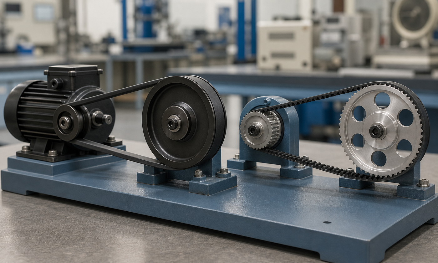
Figure 2. Both drives can reduce speed, but only the toothed drive fixes the angular relationship between shafts; the V-belt can absorb disturbance through compliance and limited slip.
Worked example 2: a timing belt for an indexing table
A light indexing table must turn at exactly one-third of its 900 rpm motor speed. It uses an 8 mm-pitch synchronous belt, a 24-tooth driver, and a 72-tooth driven pulley. The motor delivers 1.8 kW. The tooth-count ratio gives:
n2 = 900 rpm × (24/72) = 300 rpm
Unlike the fan example, no slip allowance is subtracted. The pulley pitch diameters come from circumference equals tooth count times pitch:
D1 = z1p/π = 24 × 8 mm / π = 61.1 mm
D2 = 72 × 8 mm / π = 183.3 mm
Motor torque is:
M = 9550P/n = 9550 × 1.8 kW / 900 rpm = 19.1 N·m
At the 30.55 mm driver pitch radius, the required tangential force is:
Ft = M/r = 19.1 N·m / 0.03055 m = 625 N
If starting, duty cycle, and moderate shock produce a 1.6 service factor, the design tangential force is 625 × 1.6 = 1000 N. That number does not directly select a belt width. The engineer now checks the belt maker's rating for the exact pitch, tooth profile, speed, small-pulley tooth count, engagement, width, and life target. The key interpretation is that the 3:1 ratio is kinematically exact, while the 1.0 kN design force is a strength and fatigue requirement.
Where the flat belt earns its place
Flat belts are sometimes dismissed because they need tracking attention, but they remain attractive when speed is high, the center distance is long, or very smooth running matters. Their thin section reduces bending loss as the belt enters and leaves a pulley. A slightly crowned pulley—largest diameter at its center—helps a correctly installed belt return toward the middle rather than walk off an edge.
Consider a 2.2 kW high-speed auxiliary drive running at 12 m/s. Its required effective tension difference is only 2200/12 = 183 N. If a preliminary belt construction allows 8 N/mm of effective pull after relevant corrections, the arithmetic width is 183/8 = 22.9 mm. An engineer might investigate a 40 mm standard width to provide margin for the joint, tracking disturbance, contamination, and life. As with the V-belt example, the catalog rating and actual duty replace this simplified screen.
Assumptions that can quietly invalidate the calculation
- Pitch diameter is not outside diameter. The belt's neutral load-carrying line runs at a defined pitch location. Using the visible pulley diameter can create a ratio error, especially on small pulleys.
- Power is not steady in every machine. Starting torque, reciprocating loads, jams, and frequent reversals can dominate average motor power. Apply a justified service factor and check peak torque.
- Wrap is finite. The smaller pulley often has the least contact and becomes the traction or tooth-engagement bottleneck. A very large speed ratio can reduce small-pulley wrap further.
- Temperature and contamination matter. Heat accelerates rubber aging; oil may attack or lubricate a friction belt; abrasive dust can damage teeth and pulley grooves.
- Alignment is part of capacity. Angular or offset misalignment creates unequal cord loading. A belt that carries calculated torque may still fail early because one edge is doing most of the work.
Failure modes tell you what the drive is experiencing
A glossy V-belt sidewall usually means repeated slip has heated and polished the rubber. Causes include low tension, overload, worn grooves, insufficient wrap, or contamination. Cracks across the belt often point to age, heat, or bending around a pulley that is too small. A V-belt that bottoms in the groove loses wedge action; matching belts in a multiple-belt set should be replaced as a matched set rather than mixing old and new lengths.
Flat-belt edge fraying is usually a tracking clue. Check pulley parallelism, crown condition, shaft deflection, build-up on a pulley face, and whether the belt joint is square. Simply adding tension may overload bearings without fixing the cause.
Timing-belt tooth wear or local tooth shear points toward overload, too few teeth engaged, incorrect tension, misalignment, foreign material, or an incompatible pulley profile. A synchronous drive can look normal while cords are fatigued internally, so replacement intervals and inspection history matter. Tooth jump is especially serious on machinery where phase loss can cause a collision.
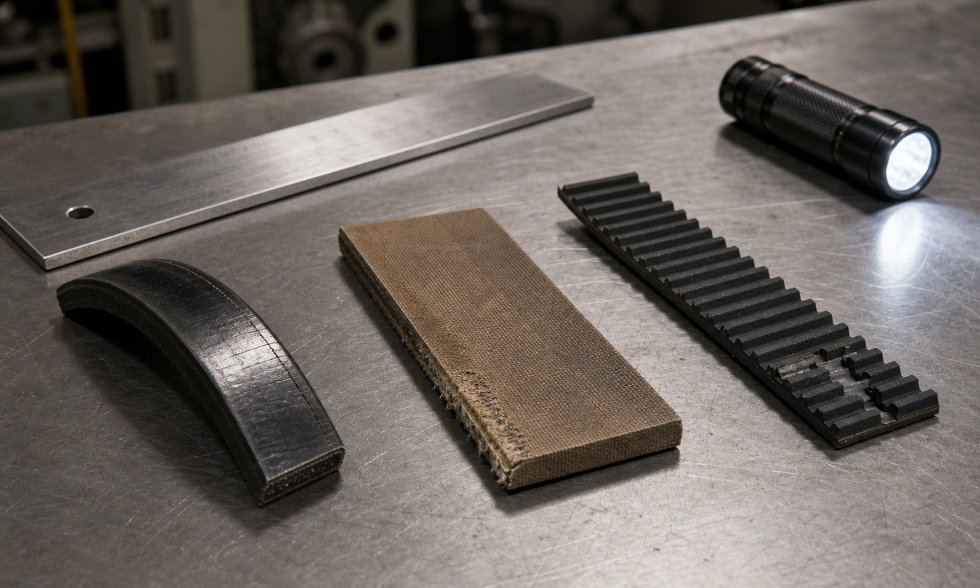
Figure 3. Treat belt damage as evidence: glazing suggests heat and slip, edge wear points to tracking, and missing synchronous teeth demand an overload and engagement investigation.
Installation choices often matter more than the belt label
Start with clean, compatible pulleys. Check groove wear with the correct gauge, verify synchronous pulley tooth profile and pitch, and do not lever a belt over a flange. Set center distance or use a proper tensioning device. Align shaft centerlines and pulley faces, rotate the drive by hand, then recheck tension after the run-in period when the product instructions require it.
More tension is not automatically safer. Excess tension increases shaft bending and bearing load, raises tooth and cord stress, and can distort light frames. Too little tension permits friction-belt slip or timing-belt tooth jump. Use the manufacturer's force-deflection, frequency, or span-vibration method for the installed geometry. A guard is required not only for personnel protection but also to keep debris away; it should still permit ventilation where heat is a concern.
How standards and catalogs fit into the decision
Standards make components interchangeable by defining dimensions, length designations, test methods, and pulley geometry. For example, ISO 4184 covers established V-belt and grooved-pulley dimensions for industrial drives. Synchronous-belt standards and industry systems similarly define pitches, profiles, widths, and measurement conventions, but tooth families are not freely interchangeable merely because their nominal pitch looks similar. Flat-belt standards and manufacturer specifications address dimensions, constructions, joints, and test conditions.
The standard gives the language and geometry; it does not perform the machine design. Final selection should use the current rating procedure for the exact belt family, including speed, pulley size, wrap, service factor, width or belt count, environmental correction, and required life. Machine guarding and reach distances should also follow the safety rules applicable to the installation and jurisdiction.
Engineering judgment: choose the failure behavior you want
Choose a V-belt when robust general-purpose power transmission, compact pulleys, inexpensive service, and some shock cushioning matter more than exact phase. Choose a flat belt when high speed, long centers, smoothness, and low bending loss justify careful tracking. Choose a timing belt when angular synchronism is a genuine functional requirement—not merely because zero slip sounds superior.
The most important question is often not “Which belt carries the most power?” It is “What should happen during overload, contamination, or misalignment?” A friction belt may announce trouble by squealing and slipping; a synchronous belt may preserve position until a tooth fails. Good design matches that behavior to the machine's risk.
For a deeper introduction to pulley ratio, wrap, and belt tension, continue with the EnggTools guide Belts and pulleys: rubber bands that move machines.