article
Tapped Hole to Clearance Hole Stackup — Circular Pattern
When bolts thread directly into tapped holes on a bolt circle — no nuts — every tiny error stacks: off-position clearance holes, an off-size bolt circle, holes a hair off their angle, and a bolt that tilts as it threads in. This beginner-friendly guide shows exactly how BCD tolerance, angle tolerance, hole EBT, coating, the projection lever-arm effect, and bolt camber combine to decide whether the bolts will assemble — with every formula and two fully worked examples.
Published Jun 03, 2026 - Maintained by Ashish Kapoor
This technical page is maintained by Ashish Kapoor, a project engineering lead. Use it as a learning and calculation-review aid, then verify critical work against current standards, project documents, supplier data, and competent engineering review.
Found an assumption, unit, formula, or standards-reference issue? Send the page URL through the contact page so it can be corrected.
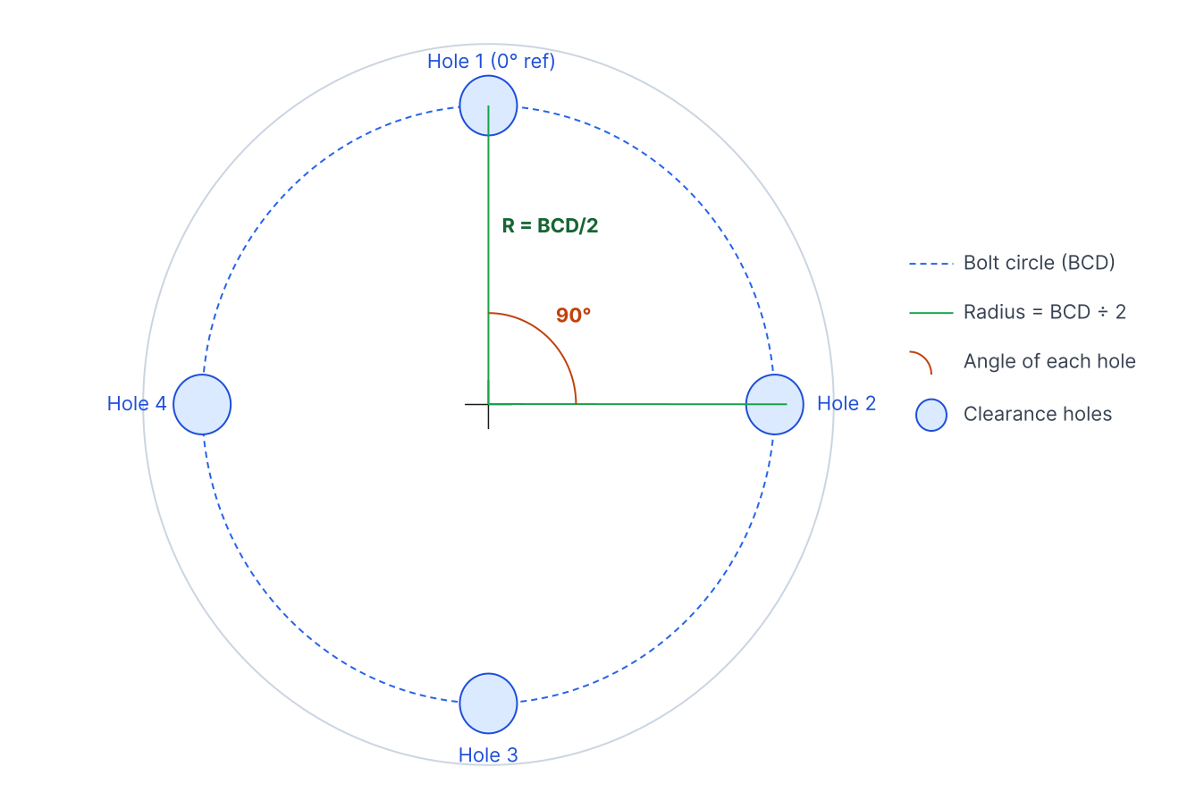 Top view of a four-bolt circular pattern. Each hole sits on the bolt circle at a set angle. The
first hole is the angle reference (0°). Instead of X/Y distances from a corner, each hole is
located by a radius (the bolt circle diameter, BCD) and an angle.
Top view of a four-bolt circular pattern. Each hole sits on the bolt circle at a set angle. The
first hole is the angle reference (0°). Instead of X/Y distances from a corner, each hole is
located by a radius (the bolt circle diameter, BCD) and an angle.
1. The problem this solves
On the drawing every hole is perfectly placed and every bolt drops straight in. Real parts are never like that. Each clearance hole is drilled a fraction off its true position. Each tapped hole is cut slightly off its own position. The bolt circle itself comes out a touch larger or smaller than nominal, and each hole lands a hair off its intended angle. The bolts are not perfectly straight either. Every error is tiny — but each bolt must pass through a misaligned clearance hole and thread into a misaligned tapped hole at the same time, so the errors stack. Push them far enough and a bolt binds in its clearance hole or misses the threads.
A tolerance stackup works out how the manufacturing variations in your parts combine, and whether the bolt still assembles through all of them. For this module: do the bolts clear the clearance holes and thread into the tapped holes on the bolt circle without interference?
This module is for holes arranged on a bolt circle and located by BCD and angle. If your holes are dimensioned by X/Y coordinates instead, use the Tapped Rectangular module — the joint behaviour is identical; only the way position error is described changes.
2. What makes a tapped stackup different
In a clearance-to-clearance joint the bolt passes through every plate and a nut closes the far end. Every plate is the same kind of obstacle — a hole the bolt must clear — and only the tightest, most misaligned hole matters.
A tapped joint changes two things, because the bottom part anchors the bolt instead of letting it slide through:
- The gap is shared, not pooled. Instead of comparing against the clearance holes alone, the available radial gap is split equally between the clearance holes and the tapped bore.
- A new contributor appears: projection tolerance. Because the tapped hole pins one end of the bolt, any position error there tilts the bolt, and the tilt grows as the bolt projects up through the stack — a lever arm. This is the defining feature of a tapped stackup and has no equivalent in clearance-to-clearance analysis.
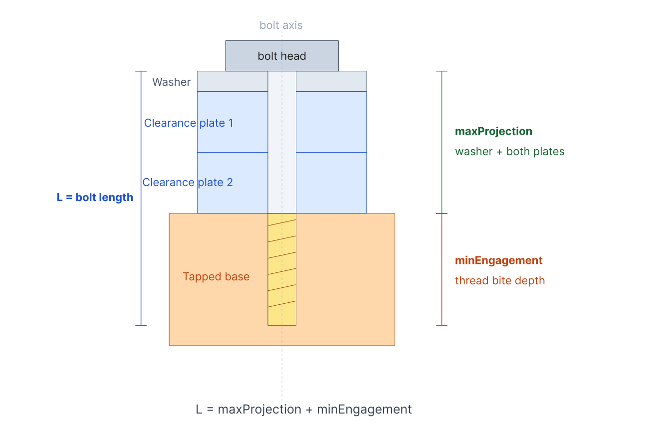 Assembled half-section with the key dimensions. The bolt spans the washer and clearance plates
(maxProjection) and then bites into the tapped base (minEngagement).
Bolt length L = maxProjection + minEngagement — the relationship the projection formula depends on.
Assembled half-section with the key dimensions. The bolt spans the washer and clearance plates
(maxProjection) and then bites into the tapped base (minEngagement).
Bolt length L = maxProjection + minEngagement — the relationship the projection formula depends on.
3. The inputs that drive the result
A handful of quantities feed the calculation. Once each is clear, the rest is arithmetic.
3a. Hole diameter and EBT
Every clearance hole has a nominal diameter and a tolerance. EBT (Equal Bilateral Tolerance) is the full permitted range: an EBT of 0.20 mm on an 11.00 mm hole means 10.90 to 11.10 mm. The worst case for assembly is the smallest hole — least room for the bolt — so the calculation uses the minimum size as its base.
3b. BCD and BCD tolerance
The BCD (Bolt Circle Diameter) is the diameter of the imaginary circle all the holes sit on — the drawing might say “4× Ø11 ON Ø80 B.C.” The BCD has its own tolerance: the actual circle may come out slightly larger or smaller. When the BCD is larger than nominal, every hole moves radially outward; when smaller, inward. That radial shift is the BCD tolerance’s contribution to position error.
Enter the total BCD tolerance range. If the drawing says BCD = 80.00 ±0.075 mm, enter BCD = 80 and BCD tolerance = 0.15 (the full range, not the half-value).
3c. Angle and angle tolerance
Each hole sits at a specified angle around the circle (0°, 90°, 180°, 270° for a four-bolt pattern). The angle tolerance is how far the actual hole angle may drift. An angular error swings the hole tangentially along the bolt circle — sideways, following the curve. Enter the total angle tolerance in degrees: ±0.05° becomes 0.10°.
3d. Coating thickness
Paint, plating, or coating builds up on the bore wall and shrinks the usable diameter. Because it coats both sides, a 0.012 mm coating removes 0.024 mm of diameter:
The tapped hole is used as-is — tapped holes are normally not coated after machining.
3e. Bolt camber
A long bolt is never perfectly straight; it bows slightly and presses on one side of the clearance hole as it tries to straighten. The module estimates this with the same empirical formula as the other stackup modules:
4. How BCD and angle tolerance become a position shift
In a rectangular pattern, position error is just √(PosTolX² + PosTolY²). On a bolt circle there are no X/Y tolerances to read off — the error comes from the BCD and the angle. So the first job is to turn those into a single radial shift, and the geometry does it in three short steps.
Step 1 — Where the hole should be (nominal)
Put the flange centre at the origin. A hole at angle θ on a circle of radius R (= BCD ÷ 2) sits at:
Step 2 — Where the hole can actually land (worst case)
Apply both tolerances at once: the radius grows by half the BCD tolerance, and the angle shifts by the angle tolerance Δθ:
Step 3 — The shift, and why it is doubled
The position shift is the straight-line distance between the nominal and actual centres. It breaks neatly into a tangential part (from the angle) and a radial part (from the BCD):
The module reports the position as a diametral value — twice the radial shift — to match how GD&T states a position tolerance (a Ø zone) and how the clearance and rectangular modules report theirs. The stackup then takes half of it back as the radial half-value, so the two cancel and what actually enters the sum is the true radial shift d. You do not have to track that bookkeeping by hand — but it explains the “2×” you see in the formula and the “0.5×” in the contributor terms.
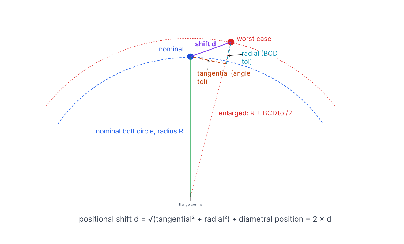 The nominal centre (blue) sits at radius R on the bolt circle. The worst-case centre (red) sits at
radius R + BCDtol/2 and angle θ + Δθ. The straight-line distance d
between them is the radial shift, splitting into a tangential component (angle tolerance) and a
radial component (BCD tolerance).
The nominal centre (blue) sits at radius R on the bolt circle. The worst-case centre (red) sits at
radius R + BCDtol/2 and angle θ + Δθ. The straight-line distance d
between them is the radial shift, splitting into a tangential component (angle tolerance) and a
radial component (BCD tolerance).
BCD = 80 (R = 40), BCD tol = 0.15, angle tol = 0.10° (Δθ = 0.001745 rad). Tangential component ≈ 0.0699 mm, radial component ≈ 0.0749 mm, so d = √(0.0699² + 0.0749²) ≈ 0.1025 mm. Diametral position = 2 × 0.1025 = 0.205 mm.
5. Projection tolerance — the one unique to tapped joints
This is the concept that defines a tapped stackup. When the tapped hole sits off true position, the bolt must tilt to thread into it. That small tilt at the base is magnified as the bolt rises through the stack: the thread engagement is the fulcrum, the shank is the lever, and the clearance hole is where the displacement lands.
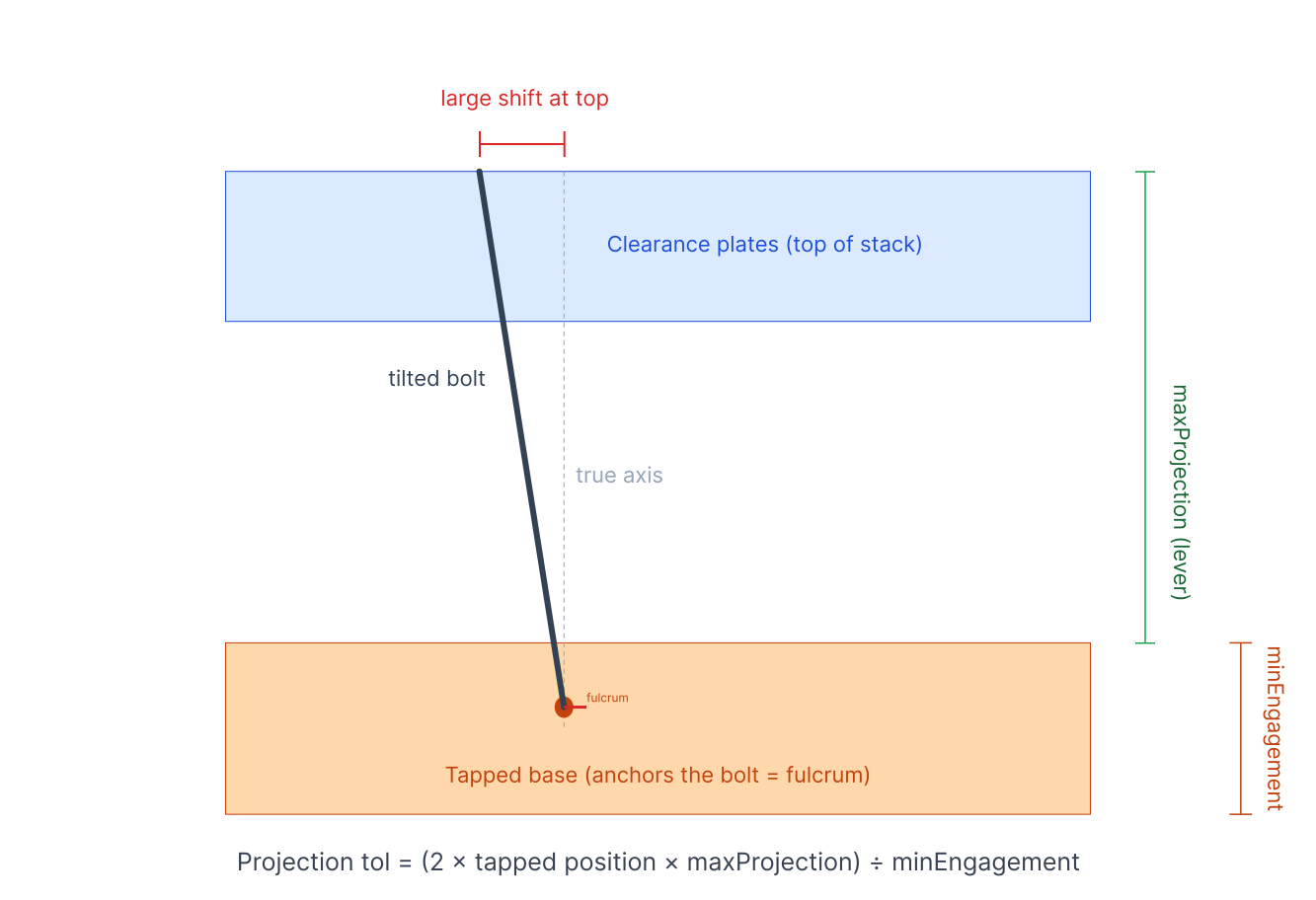 The lever-arm effect. A small position error at the tapped hole (the fulcrum) becomes a large
sideways displacement at the clearance plate. The displacement scales with the ratio of
maxProjection to minEngagement — a longer stack or less thread engagement makes it worse.
The lever-arm effect. A small position error at the tapped hole (the fulcrum) becomes a large
sideways displacement at the clearance plate. The displacement scales with the ratio of
maxProjection to minEngagement — a longer stack or less thread engagement makes it worse.
Note that “tapped-hole position” here is the same circular position value from Section 4, computed from the tapped hole’s own BCD and angle tolerances.
Projection tolerance grows with stack height and inversely with thread engagement. A bolt that is too long leaves almost no engagement, which sends projection tolerance sky-high. Check the minEngagement output first: if it is below about one bolt diameter, treat the result as unreliable.
6. Defining the clearance
In a tapped joint the bolt meets two kinds of bore — clearance holes in the upper plates and the tapped bore in the base — and the available radial gap is split equally between them:
The 50/50 split reflects that the bolt can shift against either bore. Using the smallest effective clearance hole for the worst-case base captures the tightest interface in the joint.
The pass/fail limit is the maximum fastener diameter, not the nominal — a bolt at its largest OD in the tightest hole is the harshest realistic combination.
7. Worst-case calculation, step by step
Worst-case analysis assumes every tolerance hits its most unfavourable extreme simultaneously. It is the most conservative method: if the joint passes worst-case, every possible build works.
Example values: two clearance plates on a bolt circle (each 6 mm ±0.1 mm thick, 11 mm nominal holes), BCD = 80 ±0.075 mm, angle tolerance ±0.05°, M10 bolt 40 mm long, zinc coating 0.012 mm, washer 2 mm. The tapped base shares the same BCD and angle tolerances.
Step 1 — Circular position (all holes share BCD = 80, BCDtol = 0.15, angle tol = 0.10°)
Step 2 — Effective hole diameter (each clearance plate)
Step 3 — EBT and position contributions (radial half-values throughout)
Step 4 — Projection tolerance
Step 5 — Bolt camber
Step 6 — Sum all contributors
Step 7 — Compare against the worst-case base
A negative minimum gap means real, in-tolerance combinations exist where the bolt will not assemble. Bolt camber is the dominant contributor here (about 58% of the variance). The design needs work.
Not that every build fails — that at least one legitimate combination of in-tolerance parts fails. How many fail in practice is what the statistical analysis in Section 8 estimates.
8. The RSS method — a realistic estimate
Worst-case assumes every tolerance lands at its extreme at once. Across thousands of assemblies that practically never happens. RSS (Root Sum of Squares) treats each contributor as an independent random variable and combines them as the square root of the sum of squares:
RSS variation (0.391 mm) is far below the worst-case figure (0.918 mm). Converting to a yield with a z-score:
So the joint is worst-case UNSAFE yet about 99.95% likely to assemble. Whether that is acceptable depends on the application: a pressure-flange or lifting joint should be worst-case SAFE; a non-critical cover at 99.95% may be fine.
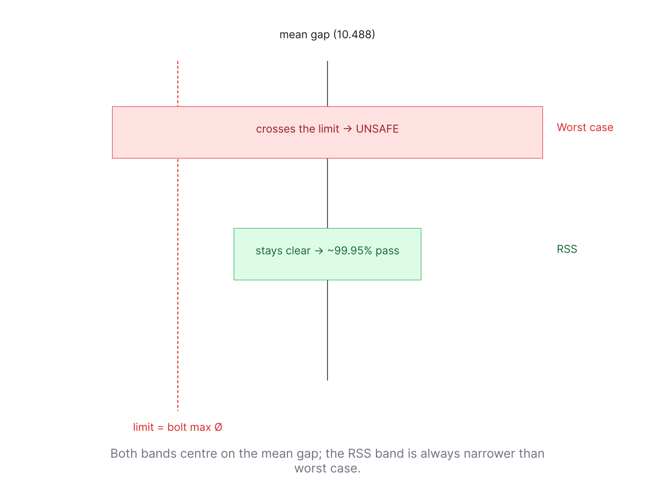 Worst-case range (red) versus RSS range (green), both centred on the mean gap. The RSS range is
always narrower. The dashed red line is the pass/fail limit (bolt max diameter). The worst-case band
crosses it; the RSS band does not — which is why yield is high even though worst-case fails.
Worst-case range (red) versus RSS range (green), both centred on the mean gap. The RSS range is
always narrower. The dashed red line is the pass/fail limit (bolt max diameter). The worst-case band
crosses it; the RSS band does not — which is why yield is high even though worst-case fails.
9. Reading the contributor chart
The tool ranks each tolerance source by its share of total RSS variance — each contributor’s term squared, divided by the sum of all terms squared. A longer bar means that source is eating more of the budget.
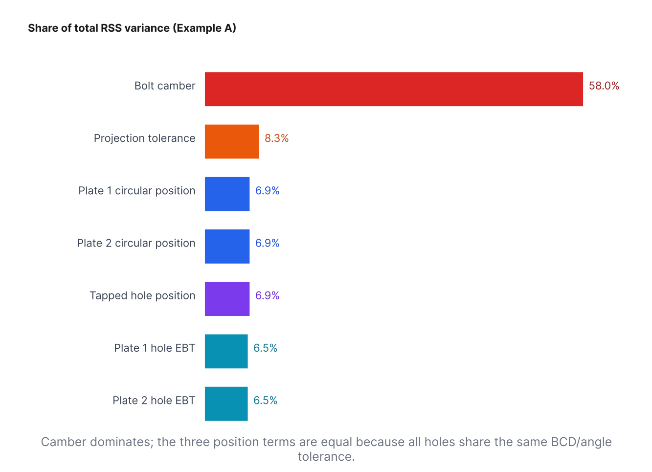 Contributor breakdown for the two-plate example. Bolt camber dominates. The three circular-position
terms are equal because every hole shares the same BCD and angle tolerance — a common situation in a
bolt-circle pattern. Projection tolerance is unique to tapped joints.
Contributor breakdown for the two-plate example. Bolt camber dominates. The three circular-position
terms are equal because every hole shares the same BCD and angle tolerance — a common situation in a
bolt-circle pattern. Projection tolerance is unique to tapped joints.
Camber and projection tolerance are usually the top contributors in a tapped stackup. That tells you where effort pays off: shortening the bolt, tightening BCD/angle on the tapped hole, or increasing thread engagement moves the result far more than tightening clearance-hole EBTs.
10. Understanding your results
| Result field | What it means |
|---|---|
| Min gap (worst-case) | Smallest possible clearance with every tolerance at its worst. Negative means some builds fail. |
| Max gap (worst-case) | Most clearance available. Useful for assembly planning, rarely the design driver. |
| Status: SAFE / UNSAFE | SAFE: even the worst combination clears the bolt. UNSAFE: at least one combination fails. |
| Statistical yield % | Probability a random build passes, under RSS assumptions and a normal distribution. |
| maxProjection | Worst-case stack the bolt spans (plates + washer). Confirm the bolt is long enough to reach the tapped hole. |
| minEngagement | Minimum thread engagement. Below ~1× bolt diameter, projection tolerance is inflated and the result is unreliable. |
11. The GD&T connection
A bolt-circle pattern on a modern drawing is usually controlled with a composite position callout referencing the BCD and angle, often with MMC modifiers. Here is how to bridge it to this module.
Position zone to circular position
GD&T states position as a cylindrical zone — e.g. ⌀0.20 mm means the hole centre must lie within a 0.20 mm-diameter cylinder around true position. That diametral value is exactly the “circular position” the module uses. If your drawing gives the position zone directly, you can enter equivalent BCD and angle tolerances that reproduce it, or use the position zone as the diametral figure. Either way, keeping the diametral basis matches how the module reports the term.
Bonus tolerance at MMC
GD&T allows extra position tolerance as a hole grows past its smallest size (MMC). A larger hole has more room, so more position error is permitted. For this module, enter the position at the worst-case (MMC, smallest) hole size to stay conservative; the Datum Shift module handles full bonus budgeting.
12. Fixing a failing stackup
If the result is UNSAFE or the yield is low, use the contributor chart and start with the biggest bar — changing a small contributor barely moves the result.
| Change | Effect | Impact |
|---|---|---|
| Shorten the bolt | Cuts camber and maxProjection, raises minEngagement — three wins at once | High |
| Tighten the tapped-hole BCD / angle | Reduces tapped position, which scales projection tolerance linearly | High |
| Increase thread engagement / deeper tap | Raises minEngagement, shrinking projection tolerance inversely | High |
| Increase clearance-hole diameter | More mean gap to spend | Medium |
| Tighten clearance-hole BCD / angle | Less position contribution per plate | Medium |
| Remove the washer | Lowers maxProjection directly | Medium |
| Reduce plate-thickness tolerance | Lowers worst-case stack height | Low–Med |
| Reduce coating thickness | Larger effective hole | Low |
Shorten the bolt to the minimum functional length. It reduces camber, reduces maxProjection, and raises minEngagement — hitting the two largest contributors at once. Try it first.
13. Worked example — a passing design
Same flange, but with a shorter M10 bolt (30 mm instead of 40) and larger clearance holes (12.5 mm nominal instead of 11). BCD and angle tolerances unchanged.
| Parameter | Plate 1 | Plate 2 | Tapped base |
|---|---|---|---|
| Hole nominal Ø | 12.50 mm | 12.50 mm | 10.00 mm (tapped) |
| Hole EBT | 0.20 mm | 0.20 mm | — |
| Coating | 0.012 mm | 0.012 mm | — (none) |
| BCD / BCD tol | 80 / 0.15 | 80 / 0.15 | 80 / 0.15 |
| Angle tol | 0.10° | 0.10° | 0.10° |
| Thickness | 6.00 ±0.10 | 6.00 ±0.10 | — |
Bolt: M10, nominal 10.00 mm, max 10.058 mm, length 30 mm. Washer 2 mm.
Worst-case minimum gap is +0.250 mm — every combination clears. The larger clearance holes absorbed the variation budget. (Notice projection tolerance grew, because the shorter bolt left less thread engagement — but the extra hole diameter more than paid for it.)
Statistical check:
Both checks pass — a robust design.
Summary
The tapped circular stackup in seven steps:
- Circular position per hole = 2 × √(tangential² + radial²), built from the BCD and angle tolerances; the sum uses half of it.
- Effective hole Ø per clearance plate = nominal − 2×coating.
- EBT term = 0.5 × EBT, per clearance plate.
- Position term = 0.5 × circular position, per clearance plate and for the tapped hole.
- Projection tolerance = (2 × tapped position × maxProjection) / minEngagement, then halve.
- Bolt camber = 0.006 × length + max body overage.
- Worst-case: fails if the sum of terms exceeds (base − bolt max Ø). Statistical: use RSS of the terms for the yield.
If it fails, read the contributor chart. Shortening the bolt, tightening the tapped-hole BCD/angle, or increasing thread engagement are the highest-impact moves available.
Try it in the tool
The Tapped Circular Stackup calculator on enggtools.in does all of this automatically — enter your bolt-circle dimensions and get worst-case and statistical results with a ranked contributor chart.
Open the Tolerance Stackup Tool →Disclaimer: educational use only. Have any tolerance analysis reviewed by a qualified engineer before using it in safety-critical applications. These are standard methods — they do not replace a full drawing review, material analysis, or formal design verification.