article
Radial Shaft Seals: How a Tiny Lip Holds Gearbox Oil
See how a spring-loaded sealing lip retains gearbox oil, depends on shaft finish, manages heat and pressure, and reveals the causes of repeat leaks.
Published Jul 17, 2026
A gearbox needs a shaft to rotate through its housing, yet the same opening must keep oil inside. A rigid ring cannot follow shaft runout, and a loose clearance becomes a leak path. The familiar radial shaft seal—often called an oil seal or rotary lip seal—solves this with a thin flexible edge that rubs on the shaft while the rest of the seal stays fixed in the housing.
It looks simple enough to cost less than many gearbox fasteners, but it works at a demanding interface. The contact line may travel several metres every second, survive millions of revolutions, hold back warm oil, exclude dust, and tolerate small shaft movements. Most early leaks are therefore not caused by a mysterious bad batch of rubber. They begin with heat, pressure, shaft finish, installation damage, or motion that the lip was never meant to absorb.
What the lip, case, and spring each do
A conventional seal has an elastomer body bonded to, or molded around, a stamped metal case. The case gives the seal its diameter and stiffness so it can be pressed squarely into the gearbox bore. At the shaft, a tapered elastomer membrane ends in the primary sealing lip. A small extension spring formed into a ring—the garter spring—maintains radial lip load as the rubber relaxes and wears.
The spring side normally faces the retained oil. Pressure on that side then tends to support the lip against the shaft instead of peeling it away. Some seals add a separate dust lip on the air side, but that lip is an excluder rather than the main oil seal. Filling the space between two lips completely with grease can create its own heat and pressure, so the seal supplier's installation guidance matters.
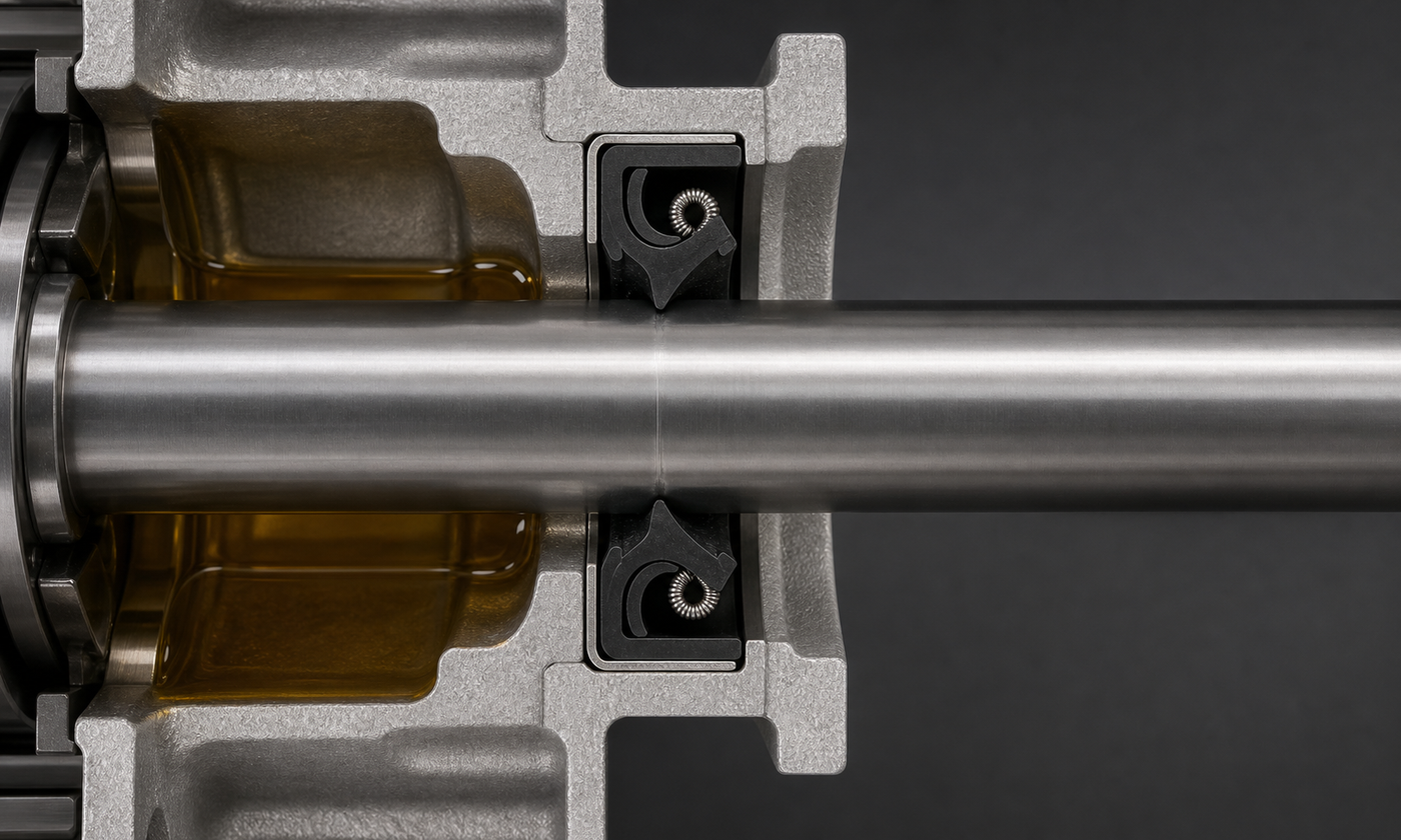
Figure 1. The metal case stays fixed in the end cover while the flexible primary lip follows the rotating shaft. The garter spring maintains contact; the oil belongs on the spring side.
The outer diameter must seal too. Rubber-covered cases accommodate modest bore roughness and differential expansion, while exposed metal cases may use a coating or sealant specified by the manufacturer. Neither style can rescue an oval, scratched, oversized, or heavily corroded bore. The press fit must both prevent leakage around the case and stop the entire seal from moving.
The seal runs on a microscopic oil film
The lip should not operate as dry rubber scraping on bare steel. At speed, a very thin oil film forms under the contact band. The lip geometry produces an asymmetric pressure distribution, and microscopic features at the interface help return oil toward the retained side. The useful film is far thinner than anything a mechanic could set with a feeler gauge: it must reduce friction without becoming a visible flow path.
This balance explains why a polished-looking shaft can still leak. A shaft finished by ordinary traverse grinding may carry a shallow helical lead. That lead behaves like a screw pump and can drag oil under the lip. The preferred running surface has controlled roughness and essentially no directional lead. It must be smooth enough not to cut the lip, but not so mirror-like that it cannot retain a lubricating film.
For many conventional elastomer seals, supplier drawings commonly begin near 0.2 to 0.8 micrometre Ra for the shaft contact surface, with a hardened wear-resistant surface often preferred when contamination or long life is important. These are useful screening values, not universal acceptance limits. Material, speed, oil, pressure, seal design, and the manufacturer's full roughness and lead requirements decide the actual finish.
Worked example 1: shaft speed and friction heat
Consider an invented conveyor gearbox with a 50 mm shaft turning at 1450 r/min. The surface speed at the seal track is:
v = πdn / 60
where v is surface speed in m/s, d is shaft diameter in metres, and n is rotational speed in r/min. Substitution gives:
v = π × 0.050 × 1450 / 60 = 3.80 m/s
Suppose a seal supplier's test data suggest a total radial lip load of 14 N at the installed diameter. For a simple screening estimate, take an effective lubricated friction coefficient of 0.18. Friction power is approximated by:
P = μFv = 0.18 × 14 × 3.80 = 9.6 W
Ten watts sounds small beside a gearbox motor, but it is concentrated around a very narrow circular track. If the oil level is low, the shaft is rough, or a dust lip adds drag, local temperature can rise enough to harden the rubber and thin the oil. The calculation is not a temperature prediction; it identifies why a modest increase in diameter or speed can matter at the seal even when gearbox power is unchanged.
The equation also exposes its limits. Lip load changes with interference, spring design, temperature, aging, and pressure. The friction coefficient changes with oil viscosity and film condition. Final selection should use the seal supplier's speed and temperature rating for the actual material and lubricant, followed by validation when the service is critical.
Pressure is often the hidden overload
A standard radial lip seal is usually a low-pressure device. Gear churning warms the trapped air, an overfilled housing leaves little expansion volume, and a blocked breather lets internal pressure rise. That pressure can distort the lip, increase contact load, push oil through the interface, or force the seal case out of its bore. A catalogue maximum is not permission to run continuously at that value; pressure capability depends strongly on speed, temperature, lip support, and seal construction.
Worked example 2: force trying to move the seal
Take a seal with a 72 mm outside diameter on the same 50 mm shaft. If a blocked breather allows gearbox pressure to rise 40 kPa above atmosphere, the pressure acts on the projected annular area between the shaft and seal outside diameter:
A = π / 4 × (72^2 - 50^2) = 2108 mm^2
Because 40 kPa equals 0.040 N/mm², the approximate axial force is:
F = pA = 0.040 × 2108 = 84 N
If pressure reached 200 kPa, the same projected force would become:
F = 0.200 × 2108 = 422 N
The lower result may be resisted by a correct press fit, but it still changes lip behavior. The higher result is a warning, not a design target: a conventional unsupported lip may leak or invert before the housing fit reaches its theoretical holding capacity. The practical fix is usually to restore ventilation, oil level, and thermal control or select a purpose-designed pressure seal—not to add adhesive and ignore the cause.
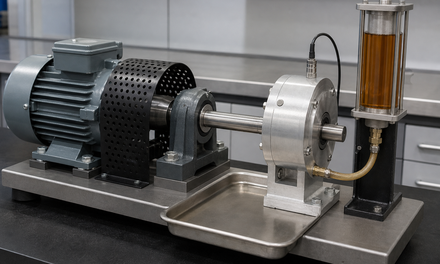
Figure 2. A seal test rig controls speed, oil supply, shaft condition, temperature, and leakage. The oil line enters the stationary chamber; nothing is connected to the rotating shaft.
The shaft is half of the sealing system
Engineers often specify the seal carefully and treat the shaft as an ordinary turned diameter. That is a mistake. The contact track needs suitable diameter tolerance, hardness, roughness, roundness, and lead. A machining spiral can pump oil outward. A soft shaft can develop a groove. Rust pits become channels. A sharp spline, thread, or keyway can slice the lip during assembly before the machine ever starts.
Runout is the repeated radial movement of the shaft surface once per revolution. Eccentricity is the offset between the shaft centreline and the seal bore. The lip has to follow both. At high speed it may lose contact on one side and be overloaded on the other. Bearing clearance, a bent shaft, an off-centre housing bore, or a cover located by loose bolts rather than dowels can create the same symptom: leakage that changes with speed.
A replaceable wear sleeve can restore a damaged track without replacing the shaft, but its thickness, finish, edge transition, installation depth, and final seal diameter must suit the seal. The new lip should normally run on an unworn track. Simply driving an identical seal to the identical depth places the new lip in the old groove and wastes the repair.
Materials must match heat, oil, and time
- Nitrile rubber (NBR) is widely used with mineral oils at moderate temperatures and offers good value.
- Hydrogenated nitrile (HNBR) can improve heat, ozone, and wear resistance in suitable fluids.
- Fluoroelastomer (FKM) serves many hotter or chemically demanding oil applications, but it is not compatible with every fluid or low-temperature duty.
- PTFE-based lips can serve higher speed, temperature, pressure, or dry-running conditions, but their geometry and installation rules differ from a spring-loaded rubber lip.
Colour is not a reliable material identification system. A seal marked for one fluid family may swell, shrink, harden, or lose strength in another. Compatibility checks must include base oil, additives, cleaning agents, water contamination, and the highest actual lip temperature—not merely ambient temperature.
Installation decides whether the first hour is successful
- Confirm the seal size, material, lip direction, shaft condition, bore condition, and installation depth before opening the package.
- Cover splines, keyways, threads, and sharp shoulders with a smooth installation sleeve or cone.
- Lubricate the primary lip with a compatible assembly lubricant unless the specified seal design requires another method. Do not leave an ordinary elastomer lip dry for startup.
- Press on the strong case area with a flat tool. Keep the seal square; hammering one edge can buckle the case or roll the lip.
- Check that the garter spring remains seated, the lip is not folded, the breather is open, and the gearbox oil level is correct.
Lead-in chamfers should be smooth and free of burrs. The housing must support the seal at the specified depth, and any retaining shoulder or circlip must be part of the original design. Adhesive is not a substitute for correct bore size. Excess sealant can migrate into bearings or oil passages.
Failure evidence and what it means
A hard, glossy lip with a wide contact band usually points toward heat, excessive interference, poor lubrication, or too much pressure. A lip cut at several locations suggests damage across splines or a sharp edge during assembly. A spring found loose may indicate an inverted or overstretched lip, incorrect handling, or pressure beyond the design.
A narrow groove in the shaft is often a combined wear and contamination problem. Dirt trapped at the contact can become an abrasive ring. Rust or fretting outside the main track suggests moisture ingress or relative movement. Leakage around the seal outside diameter points toward bore damage, poor fit, case distortion, or an unsuitable coating rather than the primary lip.
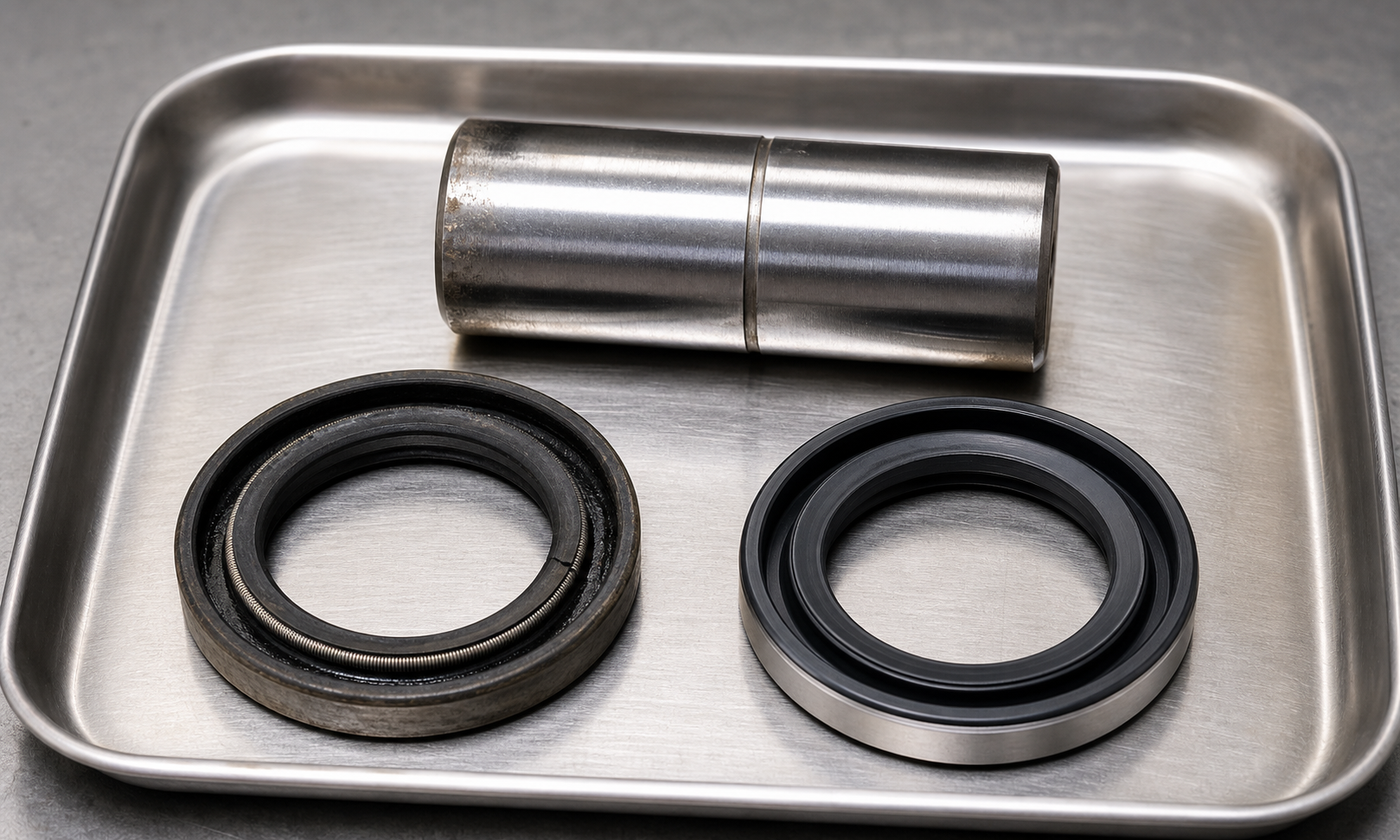
Figure 3. Compare the used seal with a clean new part and examine the matching shaft track. Replacing the rubber alone will not cure a groove, lead, runout, contamination, or blocked breather.
Record the oil level, temperature, speed, rotation direction, breather condition, shaft runout, and exact leak path before cleaning the parts. Oil sprayed around a rotating coupling may make the source look dramatic but does not identify whether it passed under the lip, around the case, along a shaft keyway, or through another joint.
How standards organize radial seal work
The ISO 6194 series provides the main international framework for rotary shaft lip-type seals. Its parts cover vocabulary and dimensions, performance test procedures, storage and handling, and characteristics of shaft and housing surfaces. DIN 3760 is also commonly encountered for radial shaft seal dimensions and application conventions. Project drawings should state the required edition, seal designation, running-surface requirements, and any supplier-specific deviations.
Standards create a shared interface; they do not select the correct elastomer, guarantee life, or approve a seal for pressure. The machine designer still defines the fluid, temperature, speed, rotation, pressure, contamination, shaft motion, bore material, and acceptable leakage. Vendor limits and validated test data must be applied to that real operating envelope.
Engineering judgment: solve the system, not the symptom
A radial shaft seal is most reliable when it is allowed to remain boring: clean oil, a vented housing, a round lead-free shaft, low runout, compatible rubber, and careful installation. If leaks repeat, look beyond seal brand. Measure the shaft, inspect the wear track, verify the breather, check bearing condition, confirm oil level, and locate the actual leak path.
The useful design question is not simply, “Which seal fits a 50 mm shaft?” It is, “Can this lip maintain a lubricated, cool, stable contact on this shaft through every speed, temperature, pressure, and contamination state the gearbox will see?” Answer that question well and the tiny lip can retain thousands of hours of operation. Ignore it and even a premium seal becomes a short-lived consumable.
Continue learning how ordinary machine parts work through the EnggTools engineering article library.