article
O-Rings: How Pressure Helps a Rubber Ring Seal Better
A simple O-ring seals by controlled squeeze, then uses fluid pressure to strengthen contact. Learn how gland geometry, clearance, material, and installation decide whether it works.
Published Jul 18, 2026
An O-ring looks almost too simple to trust: one loop of rubber sitting in a machined groove. Yet that loop can seal a pump cover, hydraulic cylinder, valve block, filter bowl, or spacecraft fluid connection. Its success comes from a useful combination of geometry and material behavior. The gland squeezes the ring enough to close the leak path before pressure arrives, then the fluid pressure pushes the rubber more firmly against the low-pressure side.
That does not make an O-ring automatic or indestructible. A ring can leak because its groove is too deep, fail because its groove is too full, extrude through a clearance gap, harden in heat, swell in the wrong oil, or be cut during assembly. Good sealing therefore begins with a simple question: can the elastomer deform through every tolerance, temperature, pressure, and motion state without losing contact or running out of space?
A seal made from controlled deformation
An O-ring is a torus—a circular cross-section formed into a continuous ring. It sits inside a gland, the groove and surrounding hardware that locate and compress it. In a static face seal, tightening a cover reduces the available gland depth so the cross-section becomes slightly flattened. The rubber bulges sideways while pressing on both mating surfaces.
This initial deformation is called squeeze. It creates contact stress even at zero fluid pressure, compensates for small surface irregularities, and prevents a continuous gap from existing across the joint. Elastomers are nearly incompressible in volume, however. Squeezing one dimension forces material into another, which is why the groove needs unused volume.
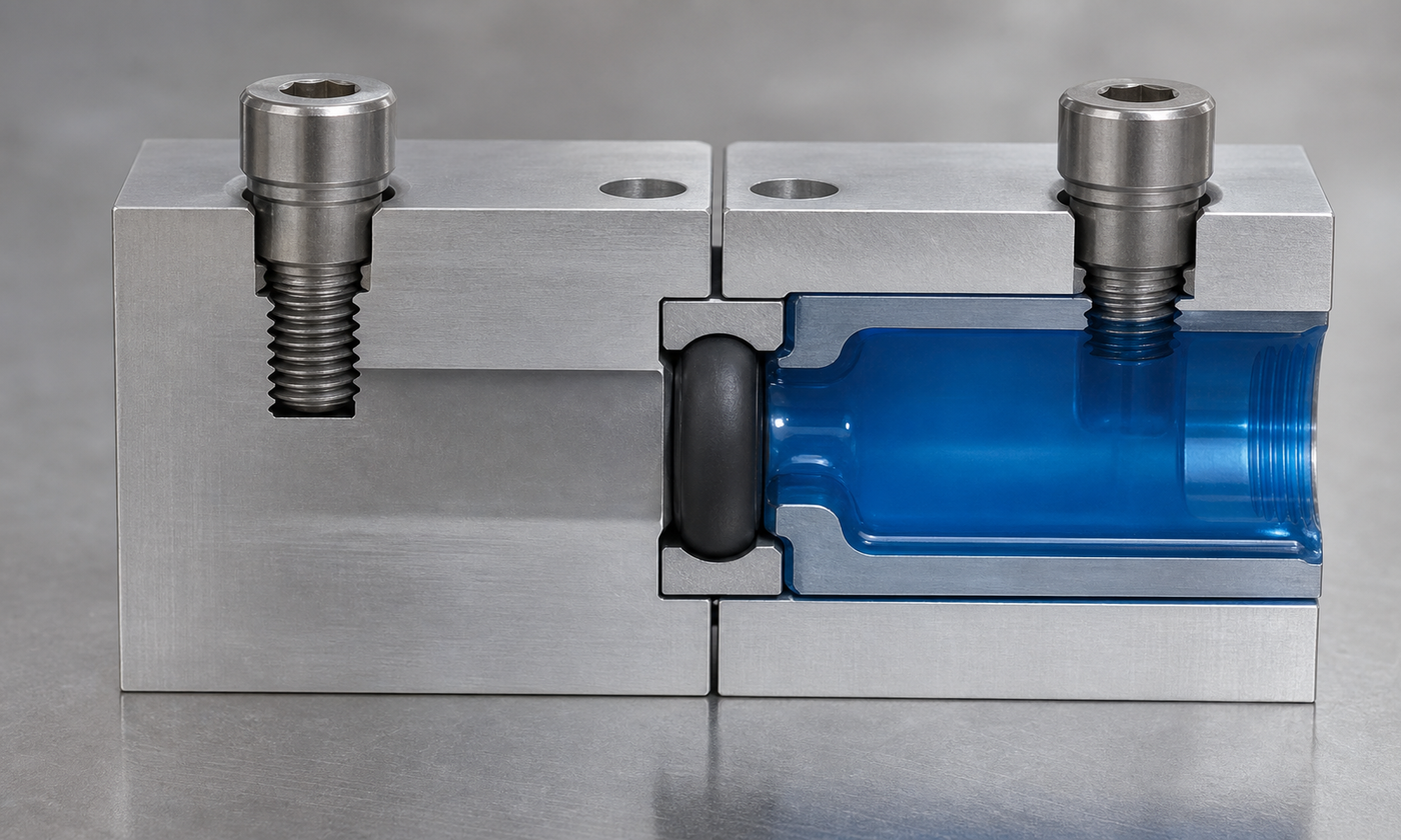
Figure 1. The gland establishes the initial squeeze. Fluid pressure from one side shifts the elastomer toward the opposite corner, increasing contact where leakage would otherwise pass.
Imagine soft modeling clay inside a partly filled tray. Press the lid down and the clay spreads into the free space. Fill the tray completely first and the lid cannot close without generating a large force or damaging something. O-ring glands behave similarly, except the elastomer must repeatedly recover its shape and remain chemically stable.
Why pressure helps instead of simply blowing the ring away
At zero pressure, the installed squeeze produces a band of contact on the gland surfaces. When fluid pressure rises, it acts on the exposed high-pressure side of the O-ring. Because the rubber transmits pressure through its body, it moves toward the low-pressure side of the groove and presses harder into that corner. The seal is therefore pressure-energized: rising system pressure adds sealing contact stress in the same region where the pressure drop occurs.
The key requirement is containment. The gland walls must support the rubber, and the clearance between mating metal parts must remain small enough that the elastomer cannot flow into it. Pressure energization is not free strength. The O-ring closes a leakage path; bolts, threads, retaining rings, cylinder walls, and covers still carry the separating load created by pressure.
Worked example 1: checking squeeze through tolerances
Consider an invented static cover seal using an O-ring with a nominal cross-section of 3.53 mm. The machined groove is 2.82 mm deep after the cover is tightened. Nominal squeeze is:
Squeeze = (cross-section - gland depth) / cross-section × 100%
Squeeze = (3.53 - 2.82) / 3.53 × 100% = 20.1%
Twenty percent is a plausible starting point for many static elastomer face seals, but the nominal number is not the design. Suppose the ring cross-section can vary from 3.43 to 3.63 mm and the assembled gland depth can vary from 2.77 to 2.87 mm.
The lowest squeeze occurs with the smallest ring and deepest gland:
Minimum squeeze = (3.43 - 2.87) / 3.43 × 100% = 16.3%
The highest squeeze occurs with the largest ring and shallowest gland:
Maximum squeeze = (3.63 - 2.77) / 3.63 × 100% = 23.7%
This tolerance check tells a better story than the nominal 20.1%. The seal should maintain useful contact at the low end without being excessively crushed at the high end. Final acceptance must use the O-ring supplier's design data for the chosen material, hardness, size, pressure, and duty. A dynamic reciprocating seal commonly needs different squeeze and friction limits from a static face seal.
Gland fill: leave room for a rubber part to behave like rubber
Gland fill compares the O-ring cross-sectional area with the available groove area. For the 3.53 mm ring, the circular cross-sectional area is:
Ring area = πd² / 4 = π × 3.53² / 4 = 9.79 mm²
Assume the rectangular groove is 4.50 mm wide and 2.82 mm deep, giving 12.69 mm² of gross area. The nominal fill is:
Gland fill = 9.79 / 12.69 × 100% = 77.1%
Now suppose fluid absorption increases the elastomer volume by 12%. As a first screening approximation, the occupied cross-sectional area also rises by about 12%:
Swollen fill = 77.1% × 1.12 = 86.4%
That result may still leave working space, while a larger swell combined with maximum ring size, minimum groove width, thermal expansion, and machining radii could approach full fill. Once the gland is effectively packed solid, thermal growth or further squeeze creates high stress, friction, nibbling, or permanent deformation. Detailed calculations should subtract corner radii and include all relevant tolerances rather than treating the groove as a perfect rectangle.
Worked example 2: pressure force belongs to the hardware
A hydraulic inspection port has a sealed diameter of 63 mm and operates at 10 MPa. The pressure acts over the projected circular area:
A = πD² / 4 = π × 63² / 4 = 3117 mm²
Because 10 MPa equals 10 N/mm², the separating force on the cover is:
F = pA = 10 × 3117 = 31,170 N = 31.2 kN
The O-ring may need only modest initial squeeze to stop leakage, but it does not hold the cover down against 31.2 kN. The bolts and cover stiffness must carry that load with an appropriate margin, while limiting flange separation. Even a small local opening can unload the seal or create a larger extrusion gap. This is why a leak blamed on “a bad O-ring” may actually be a flexible cover, weak fastener pattern, damaged thread, or excessive pressure.
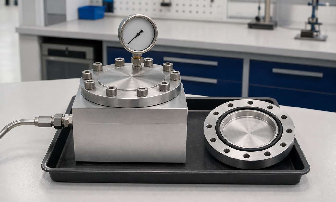
Figure 2. A controlled pressure fixture evaluates the complete joint: O-ring, gland, surface finish, fastener pattern, cover stiffness, fluid, temperature, and leakage. The gauge measures system pressure; the structure carries the separating force.
Clearance, hardness, and the extrusion problem
Under pressure, elastomer tries to enter any clearance on the low-pressure side. If the gap is large relative to pressure and material hardness, the ring develops a thin tongue that is pinched or torn as pressure cycles. This failure is called extrusion or nibbling. The damaged ring often has ragged bites along one edge rather than a uniform flat shape.
Reducing the diametral clearance, increasing elastomer hardness, lowering pressure, supporting the parts better, or adding a suitable backup ring can improve resistance. The correct choice depends on peak pressure, pressure direction, temperature, gap growth under load, motion, material, and pressure cycling. A backup ring belongs on the low-pressure side; a reversing-pressure application may need support on both sides.
Pressure spikes deserve special attention. A nominal 6 MPa circuit can briefly see much more when a valve closes quickly or a piston reaches its stop. Clearances also grow as cylinders expand, bearings deflect, and covers lift. Design against the worst credible combination, not only the gauge reading during calm operation.
Material choice is a chemical and thermal decision
- Nitrile rubber (NBR) is a common economical choice for many mineral oils and moderate temperatures.
- Hydrogenated nitrile (HNBR) can offer better heat, ozone, and wear resistance in compatible media.
- Fluoroelastomer (FKM) serves many hotter oil and fuel duties, but it is not universally compatible and may perform poorly in some low-temperature services.
- EPDM is useful with water, steam, weather, and some brake-fluid systems, but it is generally unsuitable for petroleum oils.
- Silicone elastomer retains flexibility across a broad temperature range but often has lower tear and abrasion resistance than tougher dynamic-seal materials.
Colour alone does not identify an elastomer. Compatibility must cover the base fluid, additives, cleaning chemicals, humidity, decompression rate, and actual seal temperature. Too much swell can overfill the gland; shrinkage can reduce contact; extraction of plasticizers can harden the ring. Rapid decompression of gas service can also form internal blisters when absorbed gas expands faster than it can escape.
Static, reciprocating, rotating, and vacuum duties are different
A static O-ring experiences little surface motion after assembly, so it can tolerate useful squeeze without continuous friction. A reciprocating piston or rod drags the contact band back and forth, making lubrication, finish, hardness, squeeze, and breakaway friction important. Slow rotation may be possible with a specially designed gland and material, but a conventional O-ring is usually not the first choice for a continuously rotating shaft because friction and twisting can cause spiral failure.
Vacuum sealing reverses the pressure picture and makes surface cleanliness, permeation, trapped volumes, and outgassing more important. The ring still needs initial squeeze because there may be little positive fluid pressure available to energize it. For every duty, identify which side can be at higher pressure, whether pressure reverses, and whether the ring slides, rolls, twists, or stays still.
Installation damage often happens before the machine starts
- Verify the ring size and material against the drawing and package marking; do not judge by colour or by “almost fitting.”
- Clean the groove and inspect it for burrs, corrosion, chips, paint, and sharp port intersections.
- Use a compatible assembly lubricant when permitted. Lubricant should reduce installation damage, not disguise an incorrect fit.
- Cover threads, keyways, and sharp edges with a smooth sleeve. Do not pull the ring across a burr.
- Avoid twisting. After stretching a ring over a component, let it relax and confirm that witness marks are not spiraled.
- Tighten flanges evenly so the gland closes parallel. Uneven bolt pull-down can pinch one sector before the rest is contained.
Surface finish requirements apply to the gland as well as the moving member. A deep scratch crossing the sealing contact can become a leak channel. A rough dynamic surface abrades the ring, while a sharp groove edge can shave material during assembly. Lead-in chamfers and edge breaks should guide the ring without stealing required sealing land.
What failed rings reveal
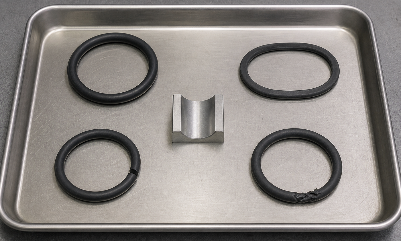
Figure 3. Failure shape is evidence. A flattened ring suggests compression set; a sharp localized slice suggests installation damage; ragged material on the low-pressure edge suggests extrusion through a clearance gap.
- Compression set: the removed ring remains flattened and does not recover. Heat, time, excessive squeeze, or unsuitable material may have reduced its elastic memory.
- Extrusion: ragged bites appear on the low-pressure edge. Check peak pressure, clearance under load, hardness, and backup support.
- Spiral failure: diagonal cuts wrap around a dynamic ring. Friction, poor lubrication, eccentric motion, or twisting in the groove may be rotating the cross-section.
- Installation cut: a clean local slice points toward threads, a burr, a sharp port, or an unsuitable assembly tool.
- Swelling or softening: the ring grows, becomes gummy, or loses strength. Confirm fluid and cleaner compatibility.
- Hardening or cracking: heat, oxidation, ozone, chemical attack, or excessive service time may be responsible.
Inspect before wiping everything clean. Record which side faced pressure, where damage sits relative to the gap, the ring dimensions, groove dimensions, fluid, temperature, pressure history, assembly lubricant, and operating time. Replacing the ring without preserving this evidence often repeats the failure.
How standards organize O-ring design
The ISO 3601 series provides a widely used framework for O-ring sizes, tolerances, housing dimensions, quality acceptance, and backup-ring guidance. AS568 size designations are also common, particularly in North American supply chains. A familiar dash number identifies a nominal size family; it does not by itself specify compound, hardness, quality grade, gland geometry, or fitness for a particular fluid and pressure.
Standards are starting points for compatible interfaces and inspection. The designer must still state the exact O-ring designation, elastomer compound or approved material requirements, hardness, service fluid, temperature range, pressure direction, motion, surface finish, groove details, and acceptance criteria. Supplier design tables should be used with the applicable edition and the actual tolerance stack. Critical pressure equipment may also be governed by system-level codes beyond the seal standard.
Engineering judgment: give the ring enough squeeze and enough freedom
A reliable O-ring gland does two apparently opposite things. It constrains the elastomer enough to create contact and resist pressure, yet leaves enough space for tolerances, heat, swell, and deformation. Chasing maximum squeeze is poor practice; so is choosing a deep groove simply to make assembly easy. The useful design lives between loss of contact and loss of free volume.
When an O-ring leaks, investigate the system before choosing a thicker ring. Check whether the leak crosses the seal or bypasses through threads, porosity, scratches, split lines, or a distorted flange. Measure the actual groove and clearance. Review pressure spikes and temperature. Confirm that the compound truly matches every fluid it touches. A simple rubber ring seals well only when the metal around it gives pressure a controlled path to make the seal stronger.
Explore more practical machine-design fundamentals in the EnggTools engineering article library.