article
Mechanical Seals: How Spinning Shafts Stop Leaks
See how flat seal faces control leakage around a rotating pump shaft, manage pressure and heat, and reveal the causes of failure.
Published Jul 16, 2026
A pump shaft has to rotate, but its casing has to hold pressurized liquid. Leaving clearance around the shaft makes rotation easy and leakage inevitable; squeezing packing tightly enough to stop every drop creates friction, heat, and wear. A mechanical seal solves the conflict with two extremely flat rings that slide against each other while allowing only a controlled microscopic fluid film between them.
The important word is controlled. A healthy mechanical seal is not a magical dry wall. A tiny amount of process liquid normally reaches the seal faces to lubricate them, remove heat, and then evaporate or emerge as leakage too small to notice. The engineering task is to keep that film stable: thick enough to prevent destructive contact, yet thin enough that leakage remains acceptable.
The face pair does the real sealing
One seal ring rotates with the shaft and the other remains stationary in the gland or housing. Their mating surfaces are annular, lapped flat, and perpendicular to the shaft. A spring or metal bellows pushes the faces together when the machine is stopped. Process pressure usually adds a hydraulic closing force during operation. Between the faces, fluid pressure and hydrodynamic effects create an opening force.
The narrow path across the face width is the primary seal. Elastomer O-rings, wedges, or bellows prevent leakage around the backs of the rings; these are secondary seals. A drive collar, pins, or tabs transmit rotation to the rotating face, while the springs allow small axial movement so the face pair can follow wear, thermal growth, and shaft movement.
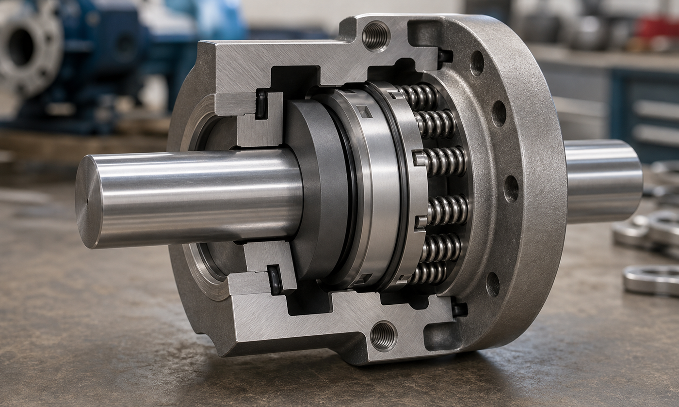
Figure 1. The primary sealing interface is the narrow annular contact between the stationary and rotating rings. Springs maintain contact at rest; pressure and the liquid film govern the operating load.
Common face combinations deliberately pair different properties. Resin-impregnated carbon graphite runs well against a hard face and can tolerate brief boundary contact. Silicon carbide offers hardness, corrosion resistance, and good thermal behavior. Tungsten carbide is tough and wear resistant but denser. The right elastomer may be nitrile, EPDM, FKM, or another compound, chosen from actual fluid chemistry and temperature rather than color or appearance.
Why a microscopic film can survive
If the faces were perfectly parallel, perfectly smooth, and pressed together everywhere, liquid could not enter. Real lapped faces contain microscopic roughness and undergo tiny elastic and thermal distortions. Rotation drags liquid into this interface. The resulting film may be on the order of a micrometre, although the actual value depends on face shape, speed, pressure, viscosity, temperature, and design. It is not an installation clearance that a technician measures with a feeler gauge.
The faces continuously negotiate three effects. Closing force tries to reduce the gap. Fluid pressure and hydrodynamic action try to open it. Heat changes viscosity and distorts the rings, which changes the gap again. A stable design finds an operating point where small disturbances correct themselves. An unstable combination can snap toward dry contact or open into visible leakage.
A balanced seal uses stepped geometry so process pressure acts on a smaller effective closing area than the full face area. Designers often describe this with a balance ratio: effective hydraulic closing area divided by face area. Values below one reduce face loading and heat at higher pressure, but too little closing margin can let the faces separate during pressure transients. The seal manufacturer's geometry and rating must therefore be used; balance is not safely improvised by machining a shoulder.
Worked example 1: estimating face loading
Consider an invented water pump seal with an outer face diameter of 51 mm and inner face diameter of 39 mm. Its annular face area is:
A = π / 4 × (51^2 - 39^2) = 848 mm^2
The seal chamber pressure is 0.45 MPa, which is also 0.45 N/mm^2. Suppose the seal geometry gives an effective hydraulic closing area of 650 mm^2. Process pressure therefore produces:
hydraulic closing force = 0.45 × 650 = 293 N
The springs add 90 N, so total closing force is 383 N. Now assume the liquid-film pressure averaged over the face produces an opening pressure of 0.18 MPa:
opening force = 0.18 × 848 = 153 N
The estimated net closing load is:
net load = 383 - 153 = 230 N
Dividing by the face area gives an average net face pressure of:
face pressure = 230 / 848 = 0.271 N/mm^2 = 0.271 MPa
This is a screening calculation, not a final seal design. It shows the scale of the load and exposes the assumptions. The average film pressure was estimated, pressure transients were ignored, and real face pressure is not perfectly uniform. The useful conclusion is that springs alone do not set the operating load; hydraulic areas and film behavior matter just as much.
Speed turns face load into heat
Sliding speed grows with both shaft speed and mean face diameter:
v = π D n / 60
where v is sliding speed in m/s, D is mean face diameter in metres, and n is speed in r/min. A first heat estimate treats the lubricated interface with an effective friction coefficient:
heat rate = μ F v
This compact expression explains why a seal that survives at low speed may fail after a speed increase even when pressure remains unchanged.
Worked example 2: friction heat and flush temperature rise
Use the 230 N net load from the first example. Let the mean face diameter be 45 mm, speed 1450 r/min, and effective lubricated friction coefficient 0.06. The sliding speed is:
v = π × 0.045 × 1450 / 60 = 3.42 m/s
The estimated face heat is:
heat rate = 0.06 × 230 × 3.42 = 47.2 W
Suppose a clean water flush passes through the seal chamber at 0.50 L/min. Taking water density as 1 kg/L gives a mass flow of 0.00833 kg/s. If all 47.2 W entered that stream and water heat capacity is 4180 J/(kg·°C), the ideal temperature rise would be:
temperature rise = 47.2 / (0.00833 × 4180) = 1.36°C
The small calculated rise suggests the flow can carry the nominal heat, but it does not prove the faces are safe. Heat splits between liquid, rings, gland, and shaft. Local flash boiling can occur even when the bulk outlet remains cool. If the film disappears, the effective friction coefficient and heat generation can rise sharply. Good design therefore checks vapor margin, start-up, low-flow operation, and loss of flush rather than relying on the steady average alone.
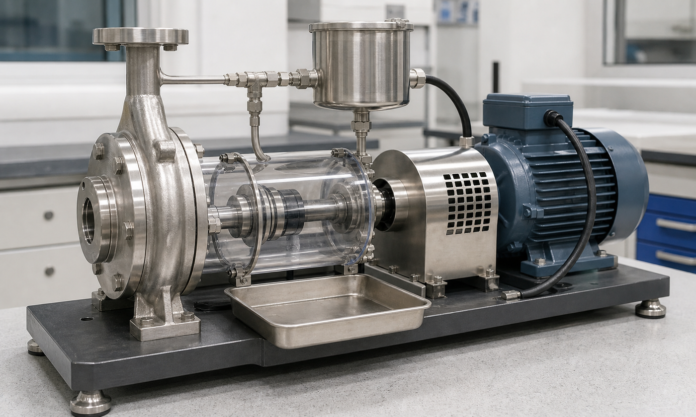
Figure 2. A controlled test rig lets engineers observe temperature, leakage, vibration, and flush behavior without exposing the rotating shaft. A dry tray is reassuring only when the seal faces also receive adequate lubrication.
Flush systems are part of the seal
A seal chamber needs liquid that is clean enough, cool enough, and sufficiently above vapor pressure. A simple clean-water pump may circulate product from a higher-pressure region back to the chamber. Hot service may use cooling or an external flush. Abrasive or polymerizing fluids may need a barrier or buffer system with two seals so the sensitive faces do not depend entirely on dirty process liquid.
More piping is not automatically better. A restriction can plug, a cooler can foul, a reservoir can be underfilled, and an incorrectly located connection can trap vapor. The piping plan must create a reliable flow path through every operating state, including starting, standby, venting, and shutdown. Commissioning should confirm direction of flow and remove trapped air before rotation.
What engineers check before selection
- Fluid: composition, solids, viscosity, lubricity, toxicity, crystallization, and compatibility with every wetted material.
- Pressure: normal chamber pressure, suction or discharge transients, vacuum conditions, and pressure during standby.
- Temperature: bulk temperature, vapor-pressure margin, heat soak after shutdown, and cooling-water availability.
- Motion: shaft speed, runout, axial movement, vibration, misalignment, and direction of rotation where relevant.
- Leakage consequence: a small water drip and a flammable toxic vapor require very different arrangements and monitoring.
- Maintenance: cartridge installation space, setting controls, cleanliness, venting, and whether the seal can be removed without disturbing major piping.
As a practical rule, protect a seal from dry running, dirty assembly, pipe strain, and excessive shaft movement before buying a more exotic face material. Face flatness is measured in optical bands by specialists; rubbing a face on workshop abrasive paper destroys the controlled geometry. O-rings should be lubricated only with a product known to be compatible, and a cartridge seal's setting clips must be removed or repositioned exactly as instructed before startup.
Failure evidence tells a story
Dry running can leave glazed carbon, heavy dust, heat checking, blisters, or cracked faces. Abrasive wear produces grooves and a widening track. Thermal shock may crack a hard face when cold liquid reaches a hot ring. Vaporization can cause noisy, unstable operation and rapid face damage as the lubricating film repeatedly collapses.
Not every leak begins at the faces. A cut O-ring, wrong elastomer, corroded sleeve, damaged gland gasket, loose drive screw, or fretted shaft can bypass a perfect face pair. Excessive runout or vibration makes the faces track axial movement every revolution, tiring springs and secondary seals. Installing a new cartridge without correcting the pump bearing, alignment, or piping problem simply starts the same failure again.
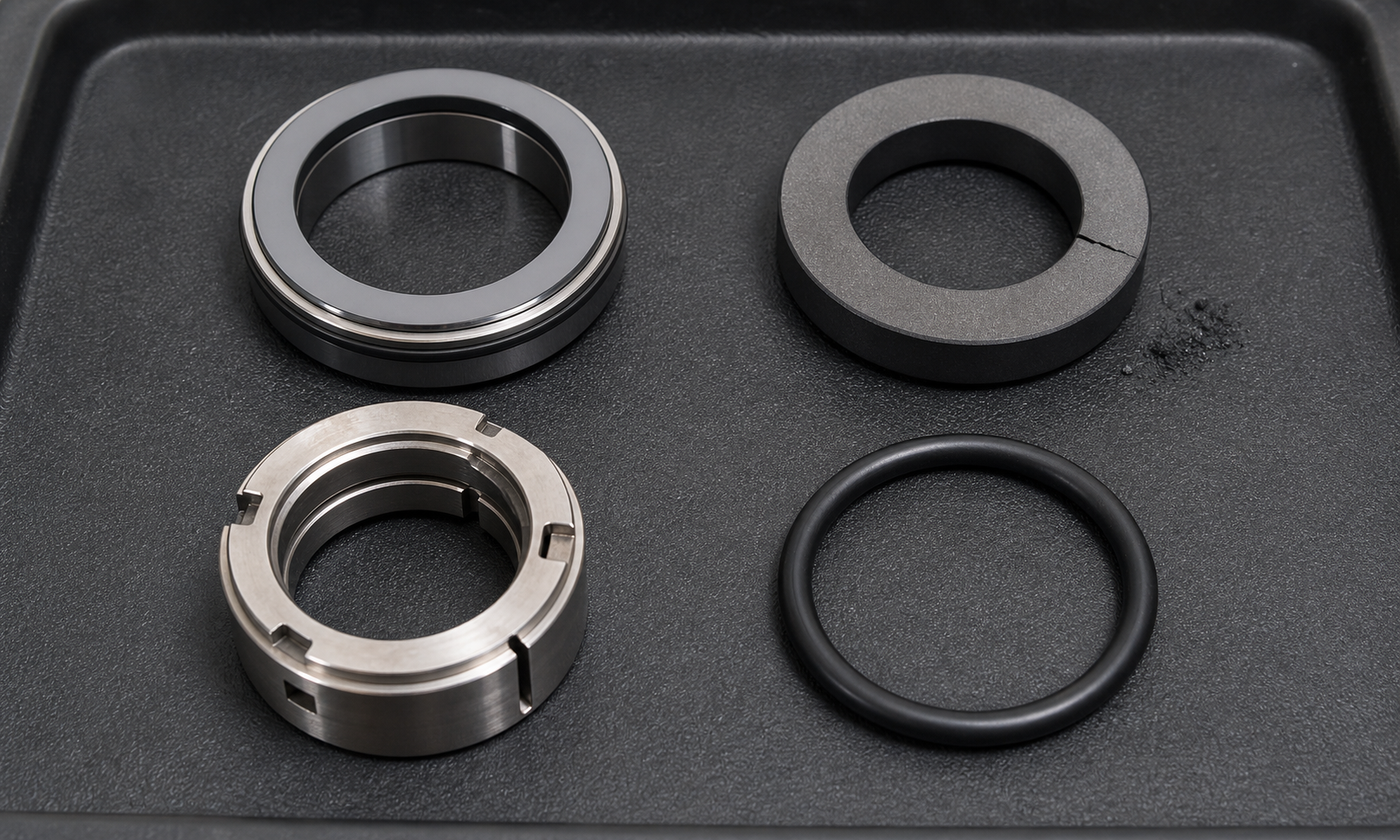
Figure 3. A narrow polished track can be normal, while a radial crack and carbon dust point toward thermal or lubrication distress. Inspect secondary seals and metal hardware as carefully as the two faces.
Failure analysis should record which side leaked, when leakage began, process conditions, flush status, vibration, and the orientation of every removed part. Paired faces should be kept together for inspection. Washing away deposits before documenting them can erase evidence of coking, crystallization, corrosion, or contamination.
How standards organize the work
API 682 and its ISO counterpart, ISO 21049, provide a common framework for mechanical sealing systems used on centrifugal and rotary pumps in demanding petroleum, natural-gas, and chemical service. They organize seal types, arrangements, materials, auxiliary piping concepts, qualification testing, and documentation. EN 12756 addresses principal dimensions and designation for common pump seals, helping equipment and seal suppliers agree on interfaces.
A standard designation is not proof that a seal will suit every liquid or operating transient. The purchaser still has to define the service correctly, apply plant and legal requirements, and review emissions, pressure equipment, hazardous-area, and machinery-safety obligations. Edition, project specification, and vendor data take priority over a remembered generic limit.
Engineering judgment: seal the operating envelope
The best seal choice is rarely the one with the highest pressure number on a catalog page. It is the arrangement that maintains a stable liquid film through the real operating envelope: cold start, hot run, low suction pressure, brief upset, standby heat soak, flush interruption, and shutdown. Reliability often comes from mundane decisions—clean assembly, a vented chamber, adequate vapor margin, sound bearings, and piping that does what the drawing intended.
Treat visible leakage as information, not merely a nuisance. Its rate, temperature, timing, and appearance can distinguish a damaged face from vapor instability or a failed secondary seal. When the cause is understood, a mechanical seal becomes more than a replaceable ring set: it is a small fluid-film machine whose behavior connects the pump, process, shaft dynamics, materials, and maintenance practice.
For more original machine-design explanations and practical calculation guides, continue through the EnggTools engineering article library.