article
Gaskets: Why Bolted Flanges Need a Softer Layer
A flange gasket seals by converting bolt preload into a continuous band of contact. Learn how seating stress, pressure, stiffness, heat, and assembly decide whether it leaks.
Published Jul 19, 2026
Two machined steel flanges can look perfectly flat and still leak. Under a microscope, each face is a landscape of grooves, waviness, scratches, and tiny high points. Tightening bare metal faces together makes contact at those high points, but it does not reliably close every connected path from the pressurized bore to the outside.
A gasket solves that problem by being deliberately softer and more conformable than the flanges. Bolt load squeezes it into the surface texture so it blocks the leak paths. The gasket does not replace strong bolts or stiff flanges; it turns their clamping force into a continuous sealing band. That distinction explains why the right gasket can seal for years and the wrong assembly can leak before commissioning.
What the softer layer actually does
A flange face has roughness at several scales. Machining marks create small channels, flange distortion creates larger low spots, and installation can add scratches or dirt. A solid steel shim may bridge those defects because it barely deforms. A gasket yields locally, flowing or compressing just enough to touch both faces across its annular area.
The useful deformation is controlled. Too little compression leaves open paths. Too much can crush fibers, buckle a metallic winding, squeeze soft material into the bore, or accelerate long-term relaxation. The joint therefore needs a seating stress: enough average compressive stress to form the seal, but below the damaging limit for the chosen gasket and facing.
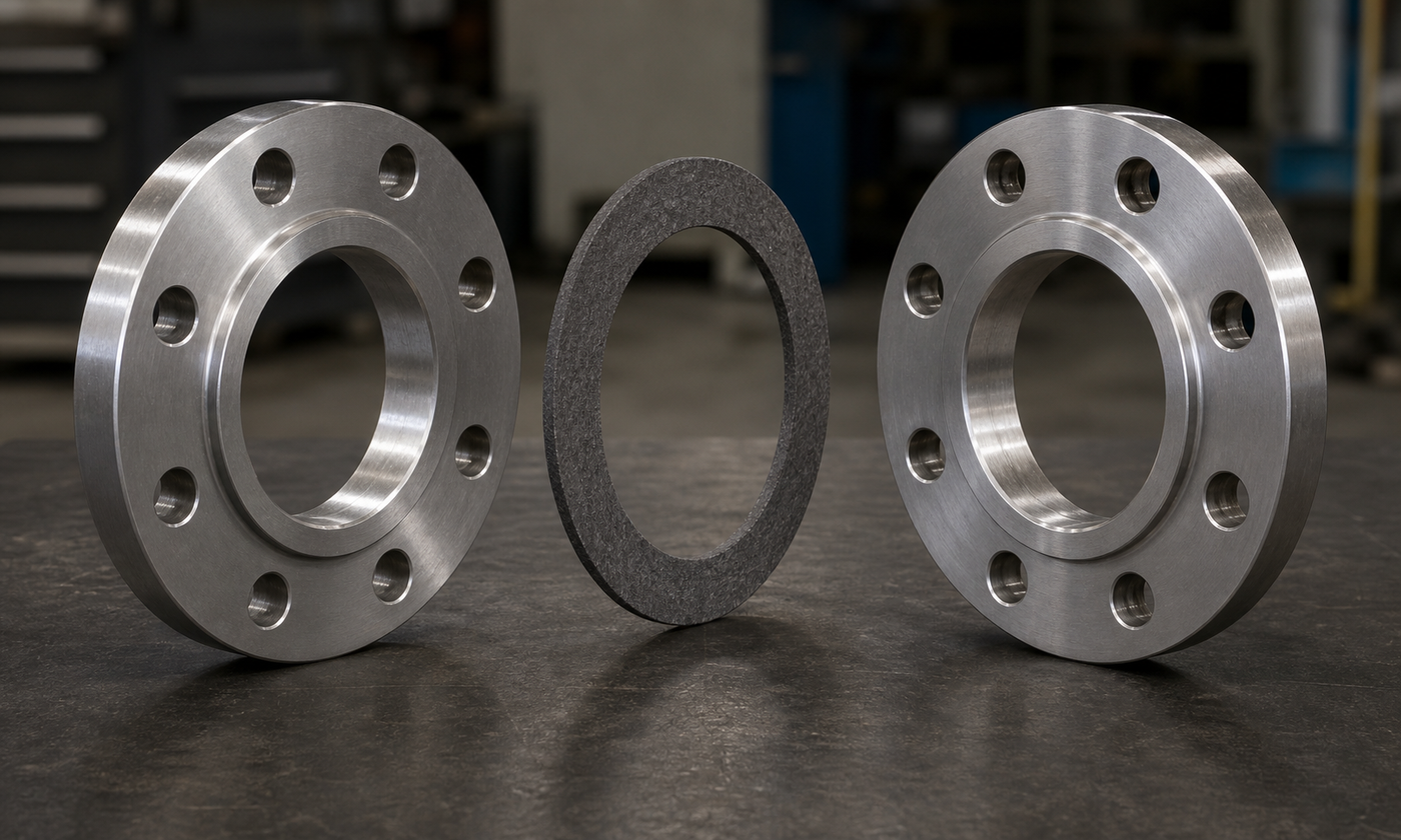
Figure 1. The steel flanges provide strength and alignment; the thin gasket provides conformity. Its bore and outside diameter must match the intended sealing land rather than obstructing the pipe or hanging beyond the raised face.
From bolt preload to gasket stress
Tightening stretches each bolt or stud elastically. That stretch creates preload, which pulls the flanges together and compresses the gasket. For a first screening calculation, the average initial gasket stress is:
Average gasket stress = total bolt preload / effective gasket area
For a simple ring with outside diameter D_o and inside diameter D_i, the gross annular area is:
A_g = π(D_o² - D_i²) / 4
This average is useful but incomplete. Real flanges rotate slightly between bolts, the gasket may have a narrower effective contact width than its visible width, and individual bolt loads scatter. Detailed pressure-joint methods account for geometry, stiffness, gasket behavior, external moments, temperature, and required leak tightness.
Worked example 1: will the gasket seat?
Consider an invented water-pump flange using a flat ring gasket with an outside diameter of 114 mm and an inside diameter of 70 mm. Eight M16 studs are tensioned to an estimated 28 kN each. The total preload is:
F_b = 8 × 28 kN = 224 kN
The nominal gasket area is:
A_g = π(114² - 70²) / 4 = 6359 mm²
Because 1 MPa equals 1 N/mm², the average seating stress is:
σ_g = 224,000 N / 6359 mm² = 35.2 MPa
Suppose the selected gasket supplier specifies an assembly window of 25 to 60 MPa for this service and facing. The nominal 35.2 MPa lies inside it. Now include an illustrative ±25% preload scatter from torque-controlled tightening. Average gasket stress could range from about 26.4 to 44.0 MPa. The low end only just clears the hypothetical minimum, showing why clean threads, controlled lubrication, calibrated tooling, and multiple tightening passes matter. The 25 to 60 MPa window is invented for this example; an actual design must use qualified data for the exact material, thickness, temperature, fluid, and flange arrangement.
Pressure tries to open the joint
Internal pressure acts over a projected area inside the joint and produces a separating force. The bolts and compressed joint members respond as an elastic system: some external load increases bolt tension, while some reduces compression in the clamped parts and gasket. A conservative first check often asks whether useful gasket compression remains after the pressure force appears.
Using an effective pressure diameter D_p, the separating force is approximately:
F_p = pπD_p² / 4
The actual load sharing depends on bolt stiffness, flange stiffness, gasket stiffness, and prying action. Simply subtracting all pressure force from preload is not a complete flange analysis, but it gives beginners a transparent screening result.
Worked example 2: compression left under pressure
Use the same 224 kN initial clamp load. Let the pump see a maximum internal pressure of 4.0 MPa and take an illustrative effective pressure diameter of 82 mm.
A_p = π × 82² / 4 = 5281 mm²
F_p = 4.0 N/mm² × 5281 mm² = 21,124 N = 21.1 kN
For the conservative screening assumption that this entire force reduces gasket compression:
Remaining clamp = 224 - 21.1 = 202.9 kN
Remaining average gasket stress = 202,900 / 6359 = 31.9 MPa
The gasket remains substantially compressed in this simplified check. That does not prove leak tightness. Pipe bending, thermal gradients, uneven bolt load, flange rotation, gasket relaxation, or a pressure surge could unload one sector long before the average reaches zero. The interpretation is therefore: pressure alone does not consume the nominal clamp, but local behavior and preload loss still need attention.
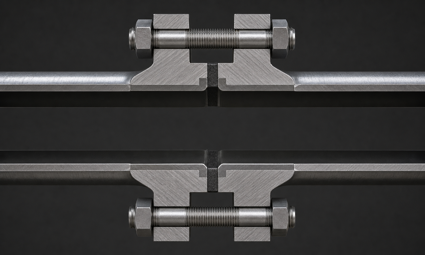
Figure 2. In the assembled joint, the gasket occupies only the annular sealing land outside the open bore. Stud stretch supplies the clamp; internal pressure and external loads try to reduce it.
Why stiffness and relaxation matter
The gasket is usually the most compliant member in the joint. During tightening it loses thickness while the studs lengthen slightly. After assembly, soft gasket materials can continue to settle through creep and stress relaxation. Surface coatings embed, fibers rearrange, and temperature changes alter material stiffness. Bolt tension then falls because the clamped stack has become thinner.
A thin gasket generally relaxes less than a thick one and is less likely to extrude, provided it can still conform to the flange condition. A thicker sheet is not a universal cure for warped faces. It can hide poor fit during assembly while creating more compressible material that later loses load. Correcting flange damage or alignment is usually better than asking the gasket to behave like a structural spacer.
Flange stiffness also controls load distribution. A flexible flange can rotate near the bolt circle, concentrating compression at one edge of the gasket and unloading another. Closely spaced, evenly loaded bolts help, but they cannot compensate indefinitely for inadequate flange thickness, severe piping moments, or misalignment forced together with the fasteners.
Common gasket families and where judgment enters
| Gasket family | Useful characteristics | Watch closely |
|---|---|---|
| Compressed fiber sheet | Conforms well and is convenient for many moderate water, oil, and utility services | Fluid compatibility, temperature, relaxation, thickness, and crushing |
| Flexible graphite | Handles many hot services and conforms to flange texture | Oxidizing conditions, handling damage, electrical or corrosion interactions, and required reinforcement |
| PTFE-based | Broad chemical resistance and low contamination potential | Cold flow, creep, temperature, flange type, and the exact filled or expanded grade |
| Spiral-wound or other semi-metallic | Useful across demanding pressure and temperature combinations when correctly supported | Correct flange facing, centering, compression control, winding damage, and required inner or outer rings |
| Metal ring type | High-integrity sealing for purpose-designed grooves and severe service | Material hardness pairing, groove condition, dimensional match, and high seating load |
No material name is a complete specification. Grade, construction, density, thickness, fillers, binders, reinforcement, facing finish, pressure, temperature, fluid chemistry, fire requirements, and emissions target all matter. Reusing a gasket is normally a poor bargain because the old compression pattern, coating damage, and unknown relaxation make its behavior uncertain.
Assembly is part of the design
- Make the joint fit freely. Correct pipe alignment before installing the gasket. Do not use the bolts to drag heavily misaligned flanges together.
- Inspect both faces. Remove old material without gouging the sealing land. Check corrosion, radial scratches, dents, and flange distortion.
- Verify the gasket. Confirm material, rating, thickness, dimensions, and orientation. Keep it clean, dry as required, centered, and undamaged.
- Prepare fasteners consistently. Use the specified studs, nuts, washers, and lubricant. Friction changes turn torque into very different bolt tension.
- Snug in a cross pattern. Bring the faces together evenly, then use several increasing-load passes rather than one full-torque pass.
- Complete a circular pass. Sequentially checking every fastener helps correct interaction as neighboring bolts are tightened.
- Record the work. Tool identification, target load or torque, lubricant, gasket batch, installer, and pass results create useful evidence.
Retightening is service-specific, not automatic. Some systems require a controlled hot or cold re-torque procedure; others prohibit it because disturbing the joint is unsafe or the gasket construction is unsuitable. The approved procedure, equipment isolation rules, and gasket manufacturer guidance govern.
Failure modes leave recognizable evidence
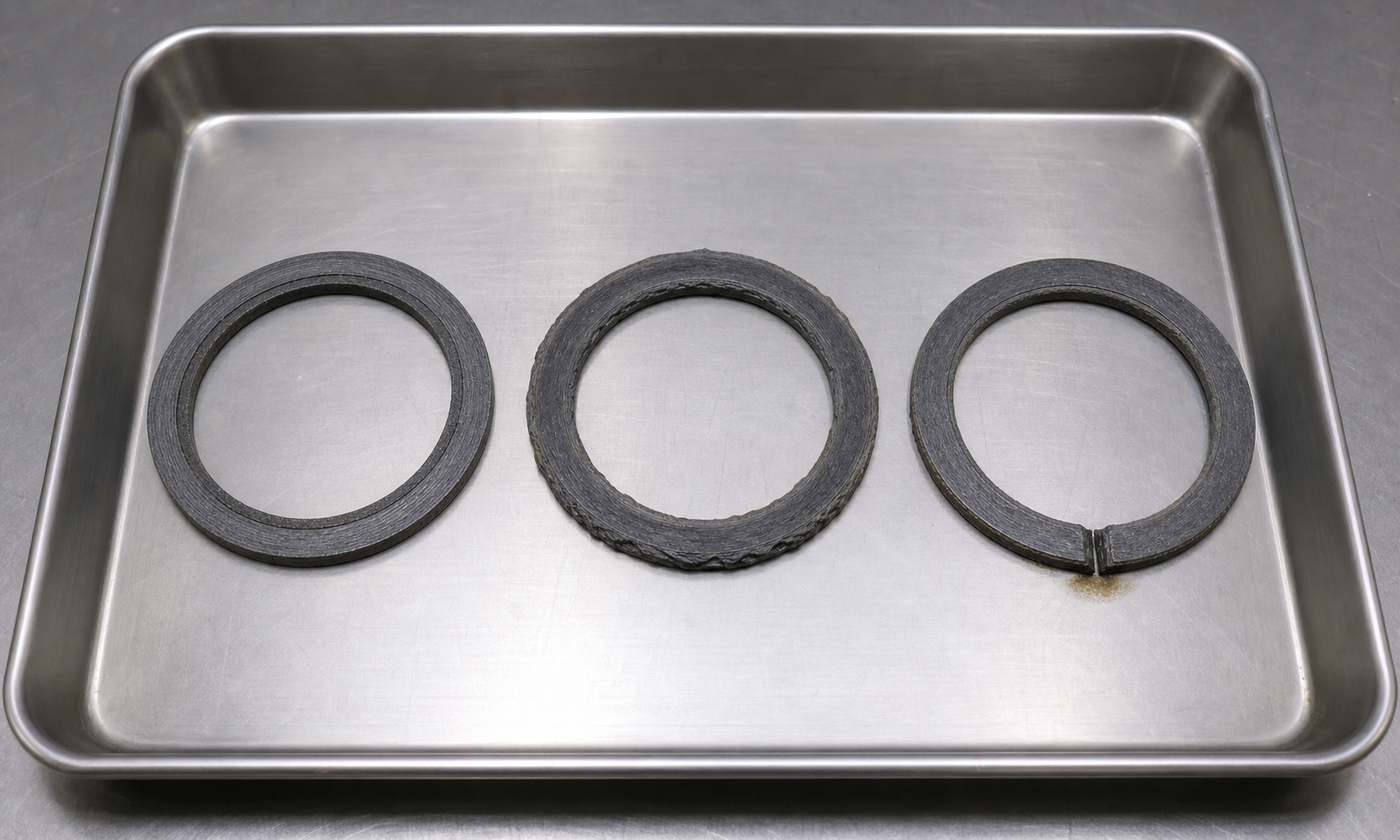
Figure 3. A uniform imprint suggests even contact. Crushed or extruded edges point toward excessive stress or poor containment. A localized blowout channel often marks the sector that first lost adequate compression.
- Insufficient seating: leakage begins during pressure testing, and the imprint is faint or discontinuous. Check bolt load, surface condition, wrong thickness, and flange parallelism.
- Over-compression: the gasket edge is heavily crushed, split, or pushed inward. Check excessive bolt load, an unsuitable soft grade, and missing compression control.
- Blowout: pressure drives material outward through a locally unloaded sector. Look for low bolt tension, flange rotation, pressure surge, external bending, or the wrong gasket geometry.
- Relaxation leak: the joint seals initially and leaks after hours or thermal cycles. Investigate gasket creep, temperature, embedment, bolt length and stiffness, and loss of preload.
- Chemical or thermal attack: the gasket becomes swollen, brittle, soft, oxidized, or bonded to the face. Confirm the actual fluid composition and metal temperature, not only the process name.
- Leak path along a scratch: a narrow stain crosses the gasket imprint in line with flange-face damage. A new gasket alone may not correct the channel.
Preserve the evidence before cleaning. Mark orientation, pressure side, top position, and the location of each stud. Photograph the imprint, measure residual bolt tension where a safe approved method exists, and compare damage with flange flatness and piping loads. A failed gasket is often the witness, not the root cause.
How standards treat flange sealing
ASME B16.5 standardizes many pipe-flange dimensions, pressure-temperature ratings, bolt patterns, and facing arrangements. ASME B16.20 covers common metallic gasket constructions, while ASME B16.21 addresses nonmetallic flat gaskets for standardized flanges. These documents help parts fit together; they do not turn every listed combination into a suitable joint for every fluid and operating cycle.
ASME PCC-1 focuses on pressure-boundary bolted flange-joint assembly, including planning, component inspection, tightening strategy, training, and quality control. More detailed design approaches, such as EN 1591 methods or pressure-vessel-code flange calculations, treat load interaction more explicitly. Project specifications may add fugitive-emissions, fire-safe, oxygen-service, food-contact, or cleanliness requirements.
The practical rule is to use the applicable edition named by the project and keep the boundary clear: flange standards define interfaces and ratings, gasket standards define products and dimensions, assembly guidance defines how preload is created, and the responsible engineer still verifies the complete operating case.
Engineering judgment: seal the joint, not just the gap
A good gasket is soft relative to the flange, but the joint around it must remain disciplined. Select a material that can conform without excessive creep. Use the thinnest suitable construction for the actual face condition. Establish a credible bolt-load window, include installation scatter, and check both initial seating and operating loads. Treat flange stiffness, alignment, temperature, external moments, and pressure cycles as part of the sealing problem.
When a flange leaks, tightening harder is not automatically the safe answer. Extra torque may recover a lightly seated joint, or it may crush the gasket, yield a stud, damage the flange, and make the next failure worse. Isolate the equipment, follow the approved procedure, and diagnose the load path. The softer layer seals only because the harder parts keep it compressed in the right place.
For a practical first estimate of fastener tension from tightening torque, use the EnggTools Bolt Pretension and Torque Calculator, then apply the gasket and flange limits required by your governing design method.