article
Couplings: Joining Two Shafts That Do Not Line Up Perfectly
See how shaft couplings transmit torque, tolerate small alignment errors, protect machinery, and reveal trouble before expensive parts fail.
Published Jul 15, 2026
A motor and a pump may be bolted to the same steel base, yet their shaft centerlines will never be mathematically perfect. The base bends slightly, feet settle, bearings have clearance, and hot machinery grows. A shaft coupling makes the rotating connection possible: it passes torque from one shaft to the other while, in many designs, allowing a small and controlled amount of relative movement.
That description needs one warning. A flexible coupling is not permission to install badly aligned machinery. Its flexibility protects the train from unavoidable residual error and movement; it should not be used to hide a bent shaft, soft foot, loose foundation, or careless alignment. Good coupling engineering is therefore a balance between transmitting power firmly and allowing just enough compliance.
What a coupling must do
At minimum, a coupling joins a driver, such as an electric motor, to a driven machine, such as a pump, fan, compressor, conveyor, or gearbox. Its first duty is to carry torque without slipping. Depending on the application, it may also:
- accept small angular, parallel, or axial movement between shafts;
- reduce shock and torsional vibration;
- electrically isolate the two machines;
- provide a replaceable sacrificial element;
- permit maintenance without moving the heavy machines; and
- fail in a predictable way before more expensive parts are damaged.
The shaft power relationship explains the basic sizing load. Mechanical power is torque multiplied by angular speed:
P = T × ω
For the units commonly used on motor nameplates, this becomes:
T = 9550 P / n
where T is torque in N·m, P is power in kW, and n is speed in r/min. A coupling is not selected from running torque alone. Starting torque, jams, reversing duty, number of starts, operating hours, temperature, and the driven machine's shock character all affect the required rating.
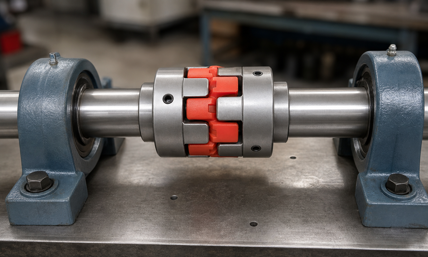
Figure 1. A jaw coupling uses two metal hubs and an elastomer insert. The hubs transmit torque through compression of the insert, which also provides limited flexibility and damping.
Three kinds of misalignment
Angular misalignment means the shaft centerlines meet at a small angle. Parallel misalignment, also called offset, means the centerlines are parallel but displaced sideways or vertically. Axial movement means the shaft ends move closer together or farther apart. Real machines usually contain a combination of all three.
A flexible element accommodates movement by elastic deformation, sliding, or a combination of both. An elastomer spider compresses between jaws. A metallic disc pack flexes like a set of thin springs. A grid slides and bends inside grooved hubs. A gear coupling permits small tooth movement while carrying high torque. Each mechanism produces reaction forces, heat, wear, or fatigue when it moves. The allowable values in a catalog are therefore limits, not desirable installation targets.
Coupling capacity also depends on combinations. A unit advertised for 0.5 mm parallel offset and 1° angular misalignment may not accept both maxima at the same time. Speed, axial displacement, and temperature can reduce the available margin further. The manufacturer's combined-misalignment chart is more useful than any single headline number.
Rigid and flexible families
A rigid coupling, such as a sleeve or bolted flange coupling, behaves almost like a continuous shaft. It is compact and torsionally stiff, but it demands excellent alignment because it provides almost no relief. Rigid couplings suit carefully supported shafts where the designer genuinely wants structural continuity; they are a poor cure for two independently mounted machines.
Elastomeric couplings use rubber-like elements in jaw, tyre, sleeve, or pin-and-bush arrangements. They are simple, damp shock, and often allow the element to be replaced without disturbing the hubs. Temperature, oil, chemicals, and age can change the elastomer's stiffness and life.
Metallic flexible couplings, including disc, diaphragm, and bellows types, avoid elastomer aging and can offer low backlash and high torsional stiffness. Their thin elements must flex without being overstrained, so correct bolt assembly and alignment are critical. Lubricated couplings, such as gear and grid types, can carry large torque in a compact envelope, but seals and lubricant condition become part of the maintenance plan.
Worked example 1: selecting torque capacity
Consider an invented centrifugal pump driven by a 7.5 kW motor at 1470 r/min. First calculate the running torque:
T = 9550 × 7.5 / 1470 = 48.7 N·m
The pump runs 16 hours per day and starts several times per shift. The project selection method assigns a service factor of 1.6 for this duty:
design continuous torque = 48.7 × 1.6 = 77.9 N·m
The motor data also gives a peak accelerating torque of 2.2 times running torque:
peak torque = 48.7 × 2.2 = 107 N·m
The coupling must satisfy both checks, so 107 N·m governs. A catalog size with a 160 N·m continuous rating and a peak rating above the motor's 107 N·m would provide useful margin. Selection is still incomplete: both finished bores must accept the actual shaft diameters and keys, the speed rating must exceed 1470 r/min, and the insert material must tolerate the ambient temperature and any oil mist.
This example also shows why simply choosing a coupling rated above 48.7 N·m is weak engineering. The motor can produce much more than its steady operating torque during acceleration or a short upset.
Alignment is still a precision job
Before alignment, the installer checks shaft and hub runout, foundation condition, pipe strain, and soft foot—a machine foot that does not sit flat on the base. Tightening a soft foot can twist the machine casing and move the shaft centerline. Rough alignment is followed by a dial-indicator or laser measurement. The machine is then corrected with horizontal movement and clean shims under the feet.
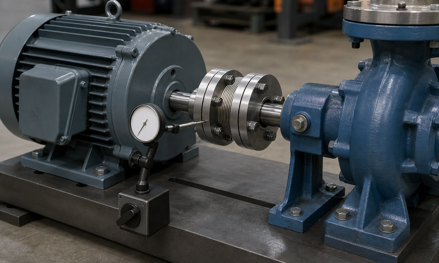
Figure 2. The coupling can tolerate residual movement, but the machine feet are still adjusted to bring the two shaft centerlines close together before operation.
Worked example 2: turning an angular reading into a shim correction
Suppose a technician measures a 0.24 mm change across opposite points of a 120 mm coupling face. For a small angle, the angular error is approximately the change divided by the measurement diameter:
θ = 0.24 / 120 = 0.0020 rad
Converting to degrees:
θ = 0.0020 × 57.3 = 0.115°
The movable machine's rear feet are 450 mm from the coupling measurement plane. The approximate shim change needed at those feet is:
shim change = θ × distance = 0.0020 × 450 = 0.90 mm
The technician would not blindly install a 0.90 mm shim and finish. The correction direction must follow the instrument setup, front and rear feet interact, and every move is followed by another complete measurement. Still, the calculation converts a small face reading into a physically understandable machine-foot correction.
Hot operation adds another layer. If a steel machine support has an effective growth length of 550 mm and warms by 55°C, using a steel thermal-expansion coefficient of 12 × 10^-6/°C gives:
ΔL = 12 × 10^-6 × 550 × 55 = 0.363 mm
That growth may be vertical, axial, or constrained by the structure. For critical equipment, engineers establish cold alignment targets that place the shafts correctly at operating temperature rather than demanding zero cold offset.
How couplings fail in service
A worn elastomer insert may harden, crack, polish, or shed particles. Repeated compression creates heat, while excessive misalignment loads one side more than the other. Increasing vibration, reddish dust, rubber debris, or a change in coupling noise are useful clues.
Metallic disc packs commonly initiate fatigue cracks near bolt holes or highly flexed regions when misalignment or assembly error is excessive. Gear couplings can wear their tooth flanks if lubrication is lost or contaminated. Hubs may fret on shafts when the fit, key, clamping force, or transmitted reversing torque is wrong. Loose fasteners and incorrect bolt grades can allow fretting and destroy carefully machined fits.
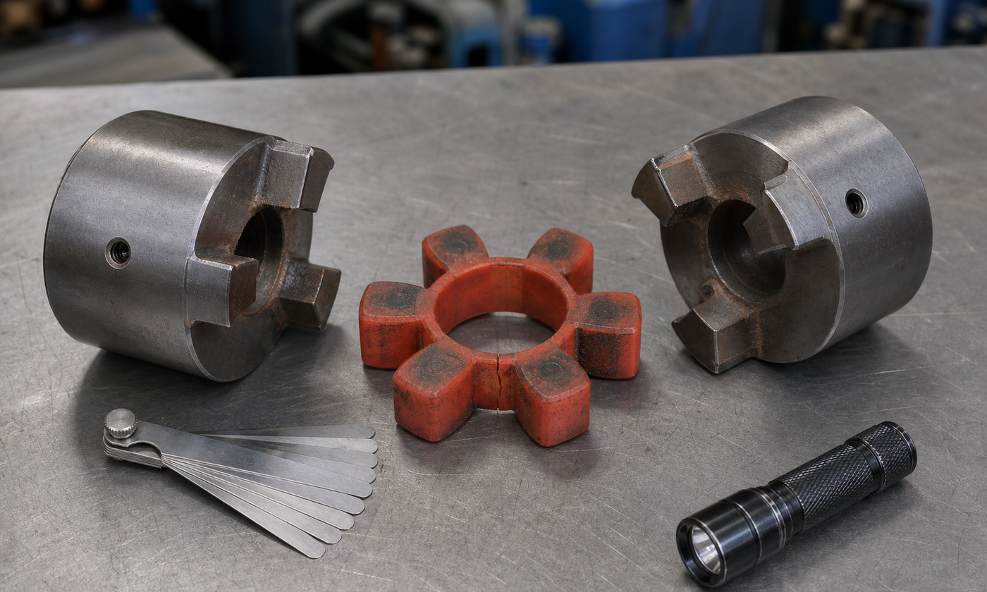
Figure 3. Contact polishing, local compression, cracking, and fretting dust can reveal overload or alignment problems. Replacing the insert without correcting the cause usually produces a repeat failure.
The coupling can also damage components around it without failing first. High reaction loads pass into motor and pump bearings, increasing vibration and seal movement. A hot bearing or leaking mechanical seal may therefore be the first visible symptom of a coupling alignment problem.
Practical selection and installation checks
- Torque: check continuous, peak, reversing, and jam loads using the project's service-factor method.
- Speed: verify maximum speed, balance quality, and any spacer-length limitations.
- Shaft interface: confirm bore range, fit, key or keyless locking method, hub overhang, and shaft-end spacing.
- Movement: compare angular, parallel, and axial requirements as a combined condition, including thermal growth.
- Dynamics: consider torsional stiffness, backlash, damping, and the possibility of torsional resonance.
- Environment: check temperature, chemicals, washdown, dust, corrosion, and lubricant compatibility.
- Maintenance: provide access for inspection and element replacement without unnecessary machine movement.
- Safety: fit a robust guard before rotation. Never run an exposed coupling for normal service.
For ordinary small machinery, final alignment errors are often measured in hundredths of a millimetre, not whole millimetres. High speed, long spacer couplings, hot machinery, or sensitive seals may demand tighter project-specific targets. The coupling manufacturer's limits and the equipment vendor's alignment requirements always take priority over a generic rule of thumb.
How standards fit into the decision
Standards do not replace the load calculation; they organize what must be specified, verified, guarded, and documented. ISO 14691 addresses flexible couplings for mechanical power-transmission applications in petroleum and natural-gas service, while API 671 is commonly applied to special-purpose couplings for demanding high-speed machinery. Balance requirements may be tied to the ISO 21940 series, and vibration acceptance may be evaluated using the applicable part of ISO 20816. Guard design is handled through machinery risk assessment and guarding requirements rather than by the coupling rating alone.
The correct standard set depends on industry, machine criticality, purchaser specification, and jurisdiction. A workshop mixer and a refinery compressor do not need the same documentation or coupling construction, even if their calculated torque happens to match.
Engineering judgment: flexibility is a limited resource
The most useful mental model is to treat coupling flexibility as a budget. Some of it is consumed by installation error, some by thermal growth, some by shaft movement under load, and some by manufacturing tolerances. If installation uses the entire allowance, nothing remains for operation. Align the machine as well as practical, then let the coupling handle the small movements that cannot reasonably be removed.
A sound selection therefore answers more than “Will it carry the torque?” It asks what moves, how often it moves, what happens during a start or jam, how the element will age, what failure evidence will be visible, and whether maintenance staff can inspect it safely. That is how two separate shafts behave like one useful driveline without forcing every bearing and seal to pay for the difference.
For more practical machine-design explanations and calculators, continue through the EnggTools engineering article library.