article
Clutches: connecting and disconnecting spinning things
A beginner-friendly engineering guide to clutches, explaining how friction and engagement control let machines connect, slip, and disconnect rotating power safely.
Published Jul 08, 2026
A motorcycle pulling away from a traffic light, a lathe spindle starting without jerking the belt, or a packaging line clearing a brief jam all rely on the same idea: the machine sometimes needs two rotating parts to act as one shaft, and sometimes it needs them separated. A clutch is the machine element that makes that connection controllable.
Beginners often think a clutch is only for cars. In reality, engineers use clutches anywhere they need smooth starting, overload protection, easy stopping, or a temporary break in the power path. The simple job description is "connect and disconnect spinning things," but the real engineering work is deciding how much torque the clutch must carry, how much heat it must survive during slip, and how predictable the engagement must feel in service.
The plain-language picture
Imagine one rotating shaft as a person holding a spinning bicycle wheel, and another shaft as a second person trying to take over that wheel. If they grab it suddenly and rigidly, the handoff is violent. If they press gently and increase grip, the wheel speed can transfer smoothly. That controlled handoff is the heart of a friction clutch.
In a friction clutch, one surface is pushed against another so friction can carry torque from the driving side to the driven side. When the clamp force is low, the surfaces slip. As the force rises, the speed difference falls, until both sides rotate together. In a positive clutch such as a dog clutch, shaped teeth lock together with almost no intended slip. Positive clutches are efficient, but they demand speed matching or very careful engagement because they do not forgive large relative motion.

Figure 1: A dry single-plate clutch connects the engine flywheel to the gearbox input shaft by squeezing a friction disc between the flywheel and pressure plate. The splined hub lets torque enter the shaft while still allowing axial movement during engagement and release.
What a clutch really has to do
A useful clutch must satisfy four jobs at once. First, it must transmit the required torque without slipping once fully engaged. Second, it must survive the heat created while the two sides are still at different speeds. Third, it must release cleanly when commanded, otherwise the machine drags and gear changes or stopping become difficult. Fourth, it must do all that repeatedly while wear, temperature, oil condition, and alignment slowly change.
That is why engineers talk about more than just torque capacity. They also care about engagement energy, surface pressure, wear rate, release travel, and whether the application is dry or wet. A lawn mower clutch, an automotive dry clutch, and a wet multi-plate motorcycle clutch all solve the same problem, but they balance those variables differently.
The governing physics
For a friction clutch, torque comes from the tangential friction force on the rubbing surfaces. The basic idea is:
friction force = friction coefficient x normal force
If that friction force acts at some effective radius, it creates torque. A beginner-friendly design expression is:
T = n x mu x W x Rm
where T is transmitted torque in N.m, n is the number of active friction surfaces, mu is the friction coefficient, W is the axial clamp load in N, and Rm is the mean friction radius in m.
For a single dry plate squeezed between the flywheel and pressure plate, there are usually two active friction surfaces. For a multi-plate clutch pack, several discs and separator plates create many more interfaces, which is why a compact wet clutch can still carry useful torque even though wet friction coefficients are lower.
The mean radius depends on how pressure is distributed across the lining. In early sizing work, many engineers use the uniform wear assumption, which leads to:
Rm = (ro + ri) / 2
where ro and ri are the outer and inner friction radii. The assumption is practical because a clutch that has seen some service tends to wear toward this condition. It is still only a model; real pressure distribution shifts with stiffness, temperature, surface waviness, and lining condition.
During engagement, another physics limit appears: heat. While the clutch is slipping, input speed and output speed are different, so power is being lost at the interface. A simple estimate for the heat generated over a short slip event is:
Q = T x omega_slip x t
where Q is energy in J, omega_slip is average slip speed in rad/s, and t is slip time in s. That energy has to go somewhere. In a dry clutch it mostly heats the flywheel, pressure plate, and lining. In a wet clutch, some of it is carried away by oil.

Figure 2: The clutch is not only a friction disc. The flywheel, pressure plate stiffness, release mechanism, splines, and bearing support all influence smoothness, wear, and the amount of torque that can be transmitted reliably.
Worked example 1: sizing a single-plate dry clutch
A small utility vehicle engine can deliver a peak torque of 160 N.m. The designer is considering a single-plate dry clutch with two active friction surfaces, friction coefficient mu = 0.32, total spring clamp load W = 4800 N, outer friction diameter 220 mm, and inner friction diameter 140 mm. Estimate the torque capacity and judge whether it has reasonable reserve.
First convert diameters to radii:
ro = 220 / 2 = 110 mm = 0.11 m
ri = 140 / 2 = 70 mm = 0.07 m
Using the uniform-wear mean radius:
Rm = (0.11 + 0.07) / 2 = 0.09 m
Now apply the clutch torque equation with n = 2 surfaces:
T = 2 x 0.32 x 4800 x 0.09 = 276.5 N.m
The clutch can ideally carry about 277 N.m. Compared with the engine peak torque of 160 N.m, the torque reserve is:
reserve factor = 276.5 / 160 = 1.73
That is a healthy margin for a beginner sizing study. It does not mean the design is automatically correct, because pedal effort, lining pressure, hot-condition friction drop, and engagement comfort still matter. But it does show why a clutch is usually sized with reserve rather than right on the engine peak. Friction changes with wear and temperature, so a clutch that only just equals the nominal torque would soon become unreliable.
Worked example 2: why wet multi-plate clutches use many surfaces
A compact wet clutch pack for a small machine tool has friction coefficient mu = 0.10 because oil separates the surfaces. The pack has 8 active friction interfaces, clamp load W = 3500 N, outer friction diameter 180 mm, and inner friction diameter 120 mm. Estimate the torque capacity.
Again convert to radii:
ro = 0.09 m, ri = 0.06 m
Mean radius under the same simple assumption:
Rm = (0.09 + 0.06) / 2 = 0.075 m
Now calculate torque:
T = 8 x 0.10 x 3500 x 0.075 = 210 N.m
Even with a much lower friction coefficient than the dry clutch in Example 1, the wet pack still transmits about 210 N.m because it has many active surfaces. That is the core tradeoff of multi-plate designs: more plates increase torque capacity and keep package diameter small, but they also increase complexity, separator drag, oil-management demands, and heat that must be removed from the pack.
Worked example 3: checking heat during a slipping start
A conveyor clutch is transmitting 90 N.m while the driving side runs faster than the driven side by an average of 70 rad/s during launch. The slip lasts 1.8 s. Estimate the frictional heat generated.
Use the slip-energy expression:
Q = T x omega_slip x t
Q = 90 x 70 x 1.8 = 11,340 J
So the clutch must absorb roughly 11.3 kJ in that short start. That is why repeated stop-start duty is often harder on a clutch than steady running. The torque may be moderate, but frequent slip events keep pumping heat into the lining and nearby metal. A design that survives one launch can still overheat badly if it must launch every few seconds.
Assumptions and their limits
The clutch equations above assume steady clamp load, predictable friction coefficient, full surface contact, and a reasonable pressure distribution. Real machines are less polite. Friction material can glaze, oil can contaminate a nominally dry surface, centrifugal effects can change contact at high speed, and the pressure plate can lift unevenly if the release mechanism is misadjusted.
Heat calculations are also easy to underestimate. The simple equation treats average slip speed and torque as if they were steady, but actual engagement often involves a quickly changing torque curve, elastic torsional wind-up in the shafting, and a lining friction coefficient that falls as temperature rises. So first-pass calculations are useful for direction, but durability needs testing, thermal judgment, and conservative margins.
Common failure modes and what they look like
- Wear-out of the friction lining: the clutch begins to engage higher in its travel, torque capacity falls, and the unit eventually slips under load.
- Glazing: the surface becomes smooth and shiny after overheating, which reduces friction and gives grabby or inconsistent engagement.
- Hot spots and warping: repeated thermal abuse creates local hard spots or distortion, leading to judder, chatter, or pulsating torque transfer.
- Drag during disengagement: the clutch does not separate cleanly, so shafts keep turning and gear shifts become difficult.
- Release-bearing or actuation failure: the friction pack may be healthy, but the operator cannot apply or remove clamp force reliably.
- Spline fretting: small oscillatory motion at the disc hub and shaft splines causes wear debris and poor torque transfer.
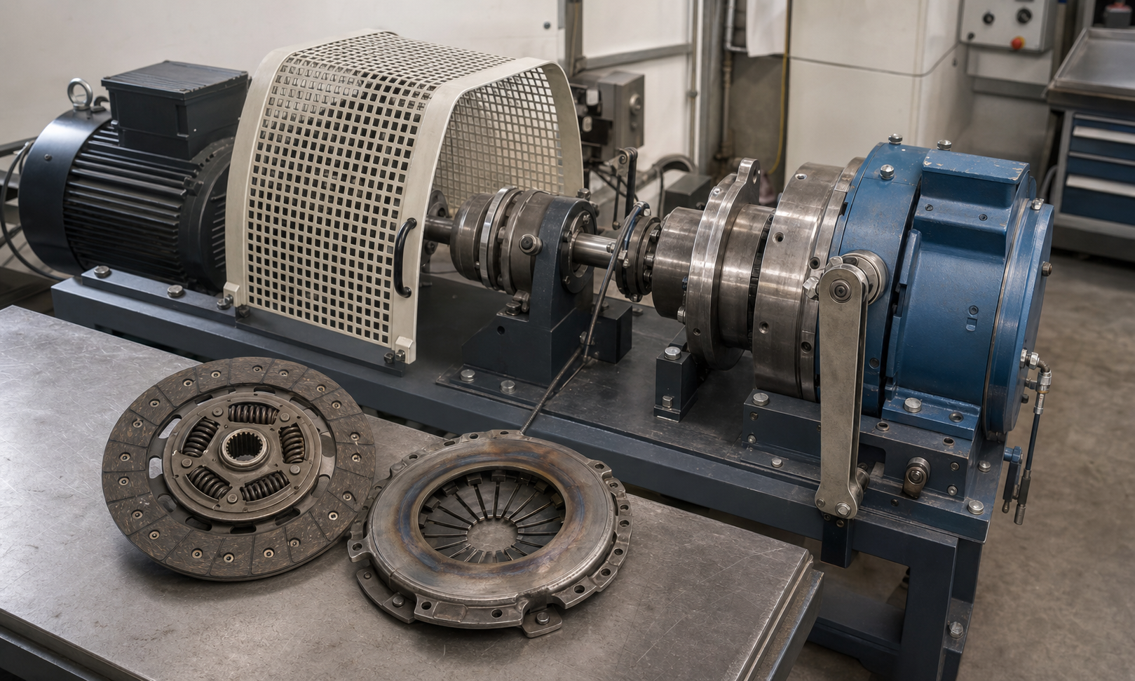
Figure 3: Clutch trouble is usually a combination problem. Torque capacity, heat rejection, actuation quality, and lining condition all interact, so a realistic test rig and careful inspection of worn parts tell more than a simple static torque number alone.
Practical rules of thumb
- Do not size a clutch exactly at nominal transmitted torque; friction and clamp load both drift in service.
- If the machine engages often or must absorb repeated launch energy, check heat first, not only static torque capacity.
- Wet clutches help with cooling and packaging, but they usually need more active surfaces because their friction coefficient is lower.
- A clutch that is too aggressive can be as troublesome as one that is too weak; very high clamp load may improve torque capacity but worsen release effort and engagement shock.
- If operators complain about chatter, inspect flatness, hot spots, contamination, and driveline stiffness together instead of blaming only the lining material.
- When the clutch sits in front of gears or belts, remember that every harsh engagement also loads shafts, keys, couplings, and bearings downstream.
How standards and design practice treat clutches
Clutch design is usually governed less by one universal "clutch code" and more by a combination of friction-material test data, machinery safety requirements, manufacturer rating methods, and application-specific standards. In practice, engineers look for proven friction coefficients under the expected temperature and oil condition, allowable interface pressure, burst-speed limits of rotating parts, actuation reliability, and safe guarding around the rotating assembly.
In industrial selection work, the standards mindset is to include service factors for shock, starting frequency, reversing duty, and thermal load, then confirm the clutch will still release and survive wear near end of life. That is a good beginner lesson: a clutch is not judged by peak torque alone. It is judged by repeatable behavior across temperature, wear, speed, and misuse.
Engineering judgment
A clutch is really a torque filter between a power source and the rest of a machine. If you want gentle starts, overload forgiveness, or easy shifting, some controlled slip is valuable. If you want maximum efficiency and absolutely no slip, a positive engagement device may be better, but only if the speeds can be matched safely. The right answer depends on duty cycle, heat, package size, control method, and what the downstream drivetrain can tolerate.
When you review a clutch concept, ask five questions in order. How much steady torque must it hold? How much slip energy must it absorb? How often will it cycle? How cleanly must it release? And what happens downstream if engagement is abrupt? Those questions usually reveal whether the design is robust or only looks good in a static calculation.
If you want to follow the torque path after the clutch engages, continue with Shafts: the spinning backbone of every machine, or browse the full EnggTools engineering article library.